
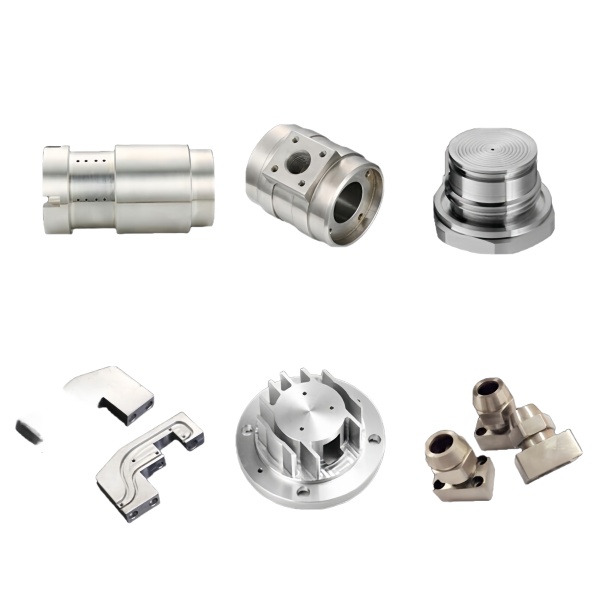
A valve housing is a pressure boundary with a hole pattern bolted to it
It is tempting to read the drawing of an aluminium valve housing as a collection of features: a bore here, a flange there, four bolt holes, two ports. That reading produces a manufacturable part and a leaking one. The correct reading is that the housing is a pressure boundary whose entire job is to contain a fluid while four or five other functions pass through it — an inlet, an outlet, an actuator stem, a mounting interface, and a sealing surface. Every feature is a penetration of that boundary, and every penetration is a place where the design either works or does not.
AUNOV machines aluminium valve housings and their mating fittings on CNC turning centres and mills, holding machined features to ±0.03 mm, and finishes them by anodizing, plating, passivation or coating according to the drawing. Aluminium is the right material for many of these housings and the wrong one for some, so the material decision deserves to be made explicitly rather than inherited from the previous design.
Why aluminium here, and when it is the wrong answer
Aluminium buys three things in a valve housing: mass, machinability, and thermal conductivity. For a manifold or a low-pressure control housing in a mobile application, saving two kilograms is worth real money over a vehicle’s life, and aluminium’s density is roughly one third of steel’s. Machining aluminium is fast, which lowers the cost of complex internal geometries. And the thermal conductivity means the housing does not become a heat trap for whatever fluid or actuator it contains, which matters when the medium is temperature-sensitive or when the actuator generates heat.
What aluminium does not buy is everything else. Its modulus is roughly one third of steel’s, so a housing designed for stiffness rather than strength will need thicker walls, which erodes the mass advantage. It has no fatigue endurance limit, so any design loaded cyclically must be assessed against a finite life and cannot rely on an infinite-life assumption. Its corrosion behaviour depends entirely on the passive oxide layer, which is stable in a near-neutral pH range and unstable outside it. And its surface is soft enough that a sealing face will scratch, dent and gall if it is handled or bolted carelessly.
| Property | Effect on a valve housing design |
|---|---|
| Modulus roughly a third of steel | Deflection under fluid pressure and bolt load is larger; flange thickness must increase to hold a seal |
| No fatigue endurance limit | Cyclic pressure or actuator loads must be designed to a finite life target, not to an infinite-life stress |
| Passive oxide, pH dependent | Stable roughly between pH 4 and pH 9; alkaline or strongly acidic media need a barrier coating, not bare aluminium |
| Galvanic potential well below steel | Aluminium becomes the anode when coupled to steel fasteners or fittings, so the couple must be broken or the area ratio managed |
| High thermal conductivity | Good for heat dissipation, bad if the intent was to insulate a hot or cold medium |
| Soft and galls easily | Threads in aluminium need inserts or extra engagement; sealing faces need protection through handling |
Sealing faces: the geometry that decides whether the part works
The sealing face is where a valve housing earns its reputation. There are three common sealing strategies and they place completely different demands on the aluminium.
- Flat gasket face. A flat face with a compressed gasket or O-ring needs flatness across the seal track and a surface roughness the gasket can wet. For an aluminium face, a machined finish in the range of 1.6 to 3.2 micrometres Ra is typical for a soft gasket. The critical attribute is not the average roughness but the absence of circumferential scratches that cross the seal track, since a scratch is a leak path regardless of how smooth the rest of the face is. Any finishing operation that polishes in a rotating pattern across the seal track is worse than leaving it as machined.
- O-ring in a machined groove. The groove dimensions are calculated from the O-ring’s cross-section, its squeeze target and the expected thermal excursion. On aluminium, both the housing and the mating part grow when hot, and if they are different materials the groove depth effectively changes with temperature. The groove width must account for the O-ring’s thermal expansion and for the volume displacement of the squeezed material, and the groove floor finish matters because a rough floor will abrade the elastomer.
- Metal-to-metal with a threaded fitting. This is common on ports and it is the least forgiving. The seal is formed by interference between two tapered or conical surfaces, and it works only while the interference is maintained. Aluminium against aluminium, or aluminium against stainless steel, both need a thread lubricant or an insert to prevent galling, and the assembly torque must be specified. A torque value that is too low leaks; a value that is too high either strips the aluminium threads or deforms the seat.
Port threads deserve one more comment. Cutting a tapered pipe thread into aluminium leaves a thread form with less material engaged than the same feature in steel, and it is more easily damaged by cross-threading. Where the customer’s own fitting will be assembled and disassembled in service, we recommend either a specified torque with a lubricant, a straight-thread port with an O-ring boss, or a threaded insert in a slightly thicker boss. Any of those three is better than relying on the aluminium thread to be reused repeatedly without damage.
The internal passages, and the burr rule
Internal passages in a valve housing are the features most likely to be under-specified and the ones most likely to cause a field failure. Three rules cover most of the ground.
- Every passage intersection needs a radius. Where a drilled cross-passage meets a main bore, the sharp corner left by the drill is a stress concentration and a place where a burr will sit. A generous intersection allows the cross-drilled edges to be broken properly. A radius of 0.5 mm or more at the intersection is cheap at the machining stage and impossible to add later.
- Deburring must be verified, not assumed. A burr at an internal passage that later breaks free becomes a contaminant downstream, and downstream in a valve housing means in the working clearance of the valve itself. Where the geometry allows, we specify a deburring method and inspect the result by borescope on a sample basis. Where it does not allow, the design should be changed so that it does.
- Blind passages trap fluid and chips. A drilled feature that ends in a flat-bottomed blind hole will hold fluid through cleaning and release it later. Either the passage should break through somewhere useful, or it should have a machined radius at the floor and be specified for specific cleaning verification.
Anodising a housing that has to seal and conduct
Anodizing is the default finish for aluminium and it is also the finish most often specified without thinking about what it does to the part. The anodic layer is a ceramic-like oxide grown from the aluminium itself, typically in the range of 5 to 25 micrometres for a decorative or Type II finish and considerably thicker for Type III. It is hard, abrasion-resistant and electrically insulating — that last property being the one that catches people.
Three consequences for a valve housing:
- The layer grows both outward and inward from the original surface, so every dimension grows. A bore that measured exactly at the limit before anodizing will be undersized after; a shaft will be oversized. The dimensional conversation has to state whether the drawing’s limits apply before or after the finish, and if the answer is after, the pre-finish dimensions must be adjusted accordingly. Twenty-five micrometres per surface is 0.025 mm, which is most of a typical valve-bore tolerance band.
- Masking is a design decision. Every face that must make electrical contact, every face that will carry a ground path, and every threaded feature that needs to conduct must be masked. Masking the threads of a small port is standard practice, and the drawing should say so.
- The sealed surface itself must be masked or protected if an O-ring lands on it, because a hard anodic layer can be abrasive to the elastomer over many cycles. Where the finish must remain, a smoother and thinner finish is chosen.
Bolted flanges and the load path through aluminium
A bolted flange on an aluminium housing fails in a specific way, and it is worth describing because it is unintuitive. Under internal pressure, the flange tries to rotate open about its inner edge, which means the seal track moves away from the mating face at the centre between bolts and the bolts see a prying load. The failure is therefore not usually a bolt breaking; it is a seal opening in the bay between two bolts, or a flange face taking a permanent set that shows up as a leak on the second assembly.
Three countermeasures, in ascending order of cost:
- Reduce the bay span by adding bolts. The deflection between supports varies approximately with the cube of the unsupported span, so adding one bolt in a long bay is disproportionately effective.
- Increase the local flange thickness near the bolt line rather than the whole flange, which adds stiffness where it is used and keeps mass down.
- Use a gasket with a defined compression load and a defined recovery, and specify the assembly torque correspondingly. A soft gasket that requires low bolt load is a legitimate way to compensate for a flexible aluminium flange, provided the gasket’s own relaxation behaviour is known.
Washers under the bolt heads deserve mention because they are the standard fix for a related problem. On aluminium, a steel bolt head tightened directly against the surface will cold-flow the material and lose preload over time, particularly at elevated temperature. A hardened washer spreads the load, protects the surface and keeps the preload stable. Given the modulus figures above and the creep behaviour of aluminium at even moderate temperatures, the washer is not an accessory; it is part of the joint design.
Machining strategy and what it does to the tolerances
Most aluminium valve housings are produced from a casting, a forging, or a billet depending on volume and on how much internal passage geometry is needed. Castings buy near-net shape and lose dimensional consistency; billets buy consistency and lose material. For a housing with a complex internal gallery, a casting is often the only affordable route, and then the machining operation’s first job is to find material in the right places rather than to remove a predictable allowance.
Setup count dominates cost. A housing that can be finished in two setups — one for the primary bore and face, one for the port side — is dramatically cheaper than one requiring four, because each additional setup adds fixturing time, adds a datum transfer, and adds its own contribution to the tolerance stack. The most valuable change a customer can make to a housing drawing is to consolidate features so that those needing tight relative position can be cut in the same setup. We will point out where that can be done during the manufacturability review; consolidating after the drawing is frozen means re-quoting.
The ±0.03 mm tolerance on machined features is achievable across a batch, but it is a process capability, not a universal guarantee. For bores, it requires that the boring operation be thermally stable, which is why finishes on precision bores are cut in a temperature-controlled environment. Thin aluminium walls deflect under cutting force, so a thin-wall housing will spring away from the tool and produce a bore that measures correct at the point of cut and relaxes afterwards. Where a wall is thinner than roughly 5 percent of the bore diameter, we plan the machining allowances around the deflection and verify after stress relief.
Pressure testing and what a test actually proves
A hydrostatic or pneumatic test proves that the part does not leak and does not rupture at the test conditions. It does not prove fatigue resistance, it does not prove the sealing behaviour after thermal cycling, and it does not prove that the joint will reassemble leak-tight after service. Those are separate tests and they should be specified separately if they matter.
Where a customer specifies pressure testing, we prefer to agree the test method before the design is frozen, because the test method constrains the part. A leak rate specification based on a pressure decay measurement has a sensitivity that depends on internal volume, so a small-volume housing may pass a decay test that a large-volume one fails with the same actual leak. The correct specification is a mass-flow leak rate, which is volume-independent, and it should be quoted with the test pressure, the test medium, the stabilization time and the acceptance threshold.
Specifying an aluminium valve housing
- Material and temper, and the reason for the choice if stiffness or corrosion is the driver.
- The medium, its concentration, its temperature range and whether it is continuously or intermittently present.
- The pressure range including surge, and whether it is cyclic enough to require a fatigue assessment.
- Every sealing interface with its sealing method, its face finish, and whether the finish requirement applies before or after anodizing.
- A masking list for the finish, covering electrical contacts, ground paths, threads and seal tracks.
- Flatness and parallelism on the sealing faces, with the measurement datum stated.
- Thread specifications including assembly torque and whether the joint will be disturbed in service.
- Any pressure test with the acceptance criterion expressed as a mass-flow leak rate.
Swapping cast iron for aluminium changes deflection and galvanic behaviour
Can aluminium replace a cast iron or bronze housing directly?
Sometimes, but not by copying the drawing. Aluminium’s lower modulus means the same wall sections will deflect more, and its galvanic behaviour means any steel fitting threaded into it creates a corrosion couple. A direct material substitution usually needs a wall change and a thread protection change.
How thin can a wall be before machining becomes impractical?
As a working figure, avoid going below 1.5 mm for a pressure boundary and below 1.0 mm on any wall that will be clamped or gripped in a fixture. Below those values the deflection under cutting force exceeds the tolerance you are trying to hold, and the fixture becomes the limiting feature of the process.
Does anodizing change the sealing behaviour of a face?
Yes, in two ways. It changes the dimensions, which changes the squeeze on any captured elastomer, and it produces a hard surface which is more abrasive to a moving seal. That is why sealing faces are usually masked, or finished with a thin and well-controlled anodic layer.
What is the smallest economic batch?
For a machined housing from billet, a small batch is entirely practical because no dedicated tooling is required; the setup is the fixed cost. For a cast housing, the pattern or die sets a much higher minimum. If you are unsure which route suits your volume, send the drawing with an estimated annual quantity and we will quote both.
The CNC Machining Parts range is the parent for parts like this one; tooling logic, finishing options and tolerance notes for the whole family are gathered on its overview page.
Specifications
| Item | Aluminum CNC Machined Valve Housings and Fittings |
|---|---|
| Brand | AUNOV |
| Designing | Send us your 2D drawing, or mail a sample for measurement, our engineers reply with a manufacturability assessment and pricing. |
| Tooling | Dies engineered and produced in our own toolroom, held under your part number. |
| Samples | Samples for approval come with a dimensional report and material certification. |
| Materials | Aluminium is the primary stock for this part, alongside carbon steel (SPCC / DC01), 304 / 316 stainless steel, brass and copper, per the drawing. |
| Surface finish | Plating, e-coat, powder coating, anodising or passivation as the drawing calls out, as called out on your print. |
| Processing | Staged deep drawing, with in-line annealing where the draw ratio requires, pierced and finish-machined on the same floor. |
| Equipment | On the press side, 5-250 T mechanical and 250-500 T hydraulic; CNC turning centres and a climate-controlled CMM room complete the floor. |
| Tolerance | As-drawn tolerance +/-0.1 mm, +/-0.03 mm on machined features. |
| Delivery terms | FOB as standard, DDP available for EU and US destinations, payment T/T or L/C, D/P for repeat accounts, call-off schedules and blanket orders supported. |
Related Products


Request a Quote for This Part
Send a drawing or sketch — get material advice, tooling cost and a per-piece price within 24 hours (working days).