
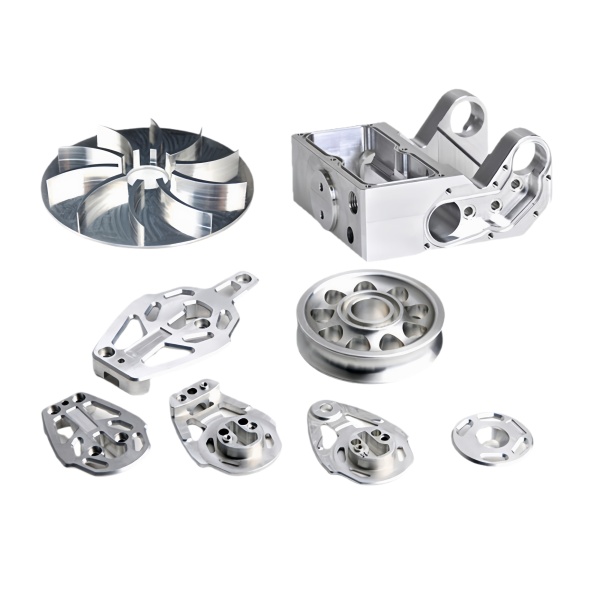
Pump body-to-impeller clearance is designed as a system, split across two separately-machined parts
An aluminum pump assembly—a machined impeller running inside a machined pump body—has its volumetric efficiency set by the running clearances between the impeller and the body’s internal surfaces: the front clearance (impeller face to body front) and the back clearance (impeller back to body’s seal land). Neither part controls the clearance alone: the axial stack-up is impeller position on the shaft (its own tolerance), plus body’s internal depth (its own tolerance), plus the shaft’s axial position in its bearing.
We machine both parts in the same dimension-control system: the body’s internal depth and the impeller’s axial width are each centered on their nominal with ±0.02 mm control, and we pair parts at assembly (measured-body-depth to measured-impeller-width, matched to land mid-clearance) rather than assembling at random. The measured stack is recorded per assembly. For replaceable-impeller pumps (customer will buy spare impellers later), we can’t pair—so we tighten both parts’ tolerances instead and publish the clearance range the customer can expect with any impeller in any body.
The pump body’s bore roundness becomes the impeller’s running clearance variation
A pump body’s internal bore—the surface the impeller’s vane tips pass close to—is usually specified on diameter alone. But an out-of-round bore (oval by 0.03 mm, well within a diameter spec) produces a clearance that varies from 0.10 mm to 0.16 mm around one revolution. The pump’s internal leakage (and thus its output at low flow) varies with clearance cubed in the narrow-gap regime: the oval bore makes the pump’s effective curve vary from one angular position to another—felt as output pulsation and low-flow instability.
We finish machine body bores with a boring pass that holds roundness to 0.01 mm and cylindricity along the bore length to 0.015 mm, verified with an inside micrometer at 3 angles × 3 depths on the first article and every 20th body. Where the drawing calls for tighter (close-clearance metering pumps), the bore is honed to 0.005 mm roundness.
Impeller bore-to-shaft fit determines whether the impeller spins true or frets
The impeller’s own bore, fitted to the pump shaft, positions the impeller. A loose fit (clearance beyond a few hundredths) lets the impeller orbit under its own unbalance reaction and under startup torque spikes—the orbit shows up as clearance variation (output pulsation) and eventually as fretting corrosion at the bore (fine aluminum oxide dust that migrates into the pump’s clearances and seals).
Our impellers are bored H7 and matched to the measured shaft size: a line-to-line to +0.015 mm clearance fit for keyed impellers, a light interference (0.010–0.020 mm) for friction-driven impellers. The bore is machined in the same setup as the vane profile and seal faces, so the impeller’s geometry (vanes, seal face, balance corrections) all references the bore—the datum that will be the shaft’s axis.
Cast vs. machined-from-bar aluminum for pump bodies: porosity and pressure testing
Machined-from-bar pump bodies (our default for this product family) carry no casting porosity—every cubic millimeter of the pressure boundary is wrought material with proven density. Cast bodies (A356 or similar) offer complex internal passages at lower cost for volume, but every cast body is a porosity lottery: a porous casting weeps at test pressure, and the porosity distribution means sample testing can’t guarantee the untested ones.
When a customer specifies cast bodies, we hydrostatically test every body (not a sample) at 1.5× rated pressure with a 10-minute hold, and we resin-impregnate any body that weeps before retest. For machined-from-bar bodies, our same 100 % hydro test has essentially never failed on porosity—the failures we do find are handling nicks on seal faces, which are caught and re-faced. The pressure-test records per serial number go with the shipment.
How we verify impeller-and-body assemblies before shipping
- Body: Bore roundness/cylindricity (inside mic, 3×3), internal depth (depth mic), seal land flatness (0.01 mm) and perpendicularity to bore, port threads (go/no-go).
- Impeller: Bore (gauge + match to shaft data), axial width, seal face runout on arbor (0.01 mm), dynamic balance (G6.3 standard, G2.5 for speeds above 5,000 RPM).
- Clearance stack: Measured body depth, impeller width, and (if we assemble) shaft axial position—recorded per assembly; the resulting front/back clearances must land within the design window (typically 0.10–0.25 mm each).
- Hydro test: Every body at 1.5× rated, 10 minutes; assemblies tested with the impeller and seal installed where the design allows.
- Performance test (sample per drawing): One assembly per batch on the hydraulic bench: head-flow curve at 5 points, compared to the drawing’s duty spec; vibration (velocity RMS) at duty point recorded against the ISO 10816 limit. A pump that meets dimensions but misses its curve tells us the vane geometry or clearance stack drifted—a design-level finding, not a part reject.
Parts like this one sit under the CNC Machining Parts range, whose overview page gathers the tooling logic, finishing options and tolerance notes shared across the family.
Balancing the impeller after machining
An impeller machined from bar is never perfectly balanced straight off the spindle, and an unbalanced wheel shakes the pump and shortens the seal. We balance each impeller to a stated grade after the finish cut, because balancing a blank and then machining it off is wasted effort. The balance removes only what the cut left, so the operation is light and fast when the machining held the form tightly. We mark the balance grade on the drawing and verify it on a sample, because a pump that vibrates is usually an impeller that was never balanced to the spec on the print.
Port alignment between body and volute
The pump body and its volute have ports that must line up in assembly, and that alignment is set by how the body is fixtured, not by the volute alone. We locate the body bores and the port faces from one datum so the inlet and outlet land where the volute expects them, and we check the port position against that datum rather than against a neighboring feature. A body that is dimensionally perfect but referenced to the wrong face is a pump that leaks at the flange, which is the failure mode that looks like a gasket problem and is really a datum problem.
Specifications
| Item | Aluminum CNC Machined Impellers and Pump Bodies |
|---|---|
| Brand | AUNOV |
| Designing | Send drawings, or send a body sample to be measured, a manufacturability review comes back with the quotation. |
| Tooling | Dies designed and built in our own toolroom, each die held against your part number. |
| Samples | Sample parts arrive with a full dimensional report and mill certificate. |
| Materials | Aluminium leads the stock list for this part, alongside carbon steel (SPCC / DC01), 304 / 316 stainless steel, brass and copper, and the grade is fixed at the drawing review. |
| Surface finish | Surface treatment per the drawing: plating, e-coat, powder coating, anodising, passivation, as called out on your print. |
| Processing | Deep drawing in stages, in-line annealing where needed, pierced and finish-machined on the same floor. |
| Equipment | 5-250 T mechanical presses plus 250-500 T hydraulic presses, CNC cells plus a temperature-controlled CMM room. |
| Tolerance | Drawn tolerances held to +/-0.1 mm, +/-0.03 mm on machined surfaces. |
| Delivery terms | FOB is standard; DDP offered for EU and US, T/T or L/C, with D/P for repeat business, call-off schedules supported. |
Related Products


Request a Quote for This Part
Send a drawing or sketch — get material advice, tooling cost and a per-piece price within 24 hours (working days).