
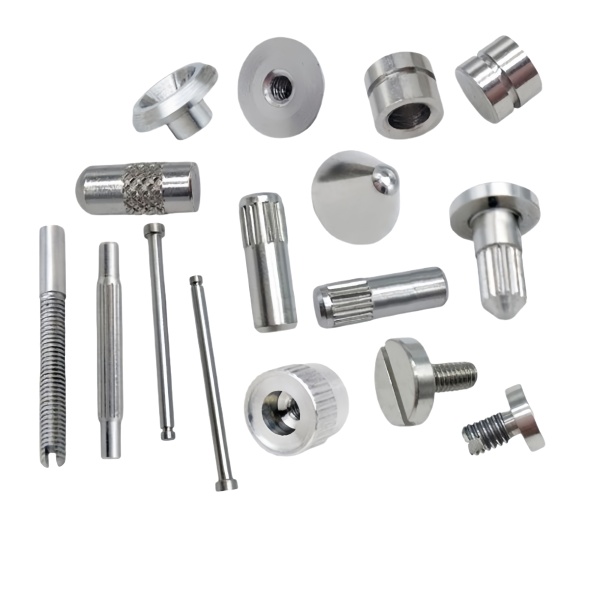
The Assorted Aluminum and Steel CNC Machined Shafts and Knobs family combines two part types that look related and behave differently in the machine: steel shafts, where concentricity between journals and straightness over length are the whole job, and aluminium knobs, where grip, feel and finish dominate. Running both in one assorted release adds a third discipline – two materials with different tooling, chip behaviour and schedules have to arrive together. This page covers how shaft runout is actually produced, what knurling demands from the material and the feed, the economics of a mixed-material family, and the verification we run before shipment.
Runout between journals is built at the setup, not measured away later
A stepped shaft is typically judged on one number: total indicator runout between its journals, the surfaces that ride the bearings. What that number really measures is the accumulated error of the setup strategy. Shaft work between centres inherits the centre-hole geometry – a centre hole that is not round or not clean puts that error directly into every journal turned from it, and 0.02 mm of centre-hole error becomes 0.02 mm of runout no matter how good the turning is. Chucked work inherits chuck repeatability and the pull-off of the tailstock; and any shaft turned in two setups, flipping end for end, inherits whatever the second setup failed to reproduce of the first.
- Journal-to-journal runout inside a single setup is essentially free – the geometry is generated by machine accuracy alone, and 0.005 mm is routine on our turning centres.
- Runout across a flip is the risk: we hold it by re-establishing from the turned centres or a machined datum diameter, and by cutting the finishing passes of both ends in setups that share that reference.
- Centre-hole preparation is treated as a machining operation with its own check – cleaned, round, and protected between operations, because a scratched centre from careless handling is the most common self-inflicted runout defect on steel shafts.
- Where the print demands runout better than about 0.01 mm across multiple flips, we say so at quotation and route the part accordingly rather than promise a number the setup cannot generate.
Turned diameters hold +/-0.005 to +/-0.01 mm by routine and bearing seats to specified fit classes, but the dimensional report only matters if the runout behind it is honest – a shaft can measure perfect at every journal and still spin badly.
Knurling is a forming operation, and the material answers for it
A knob’s knurl looks decorative but functions as grip, and grip is a mechanical property: the knurl raises the material into ridges by displacement, not by cutting, so the workpiece has to flow. The wheel pitch, the feed per revolution and the material’s ductility have to agree. Cut knurls and formed knurls behave differently – formed knurls on aluminium grip beautifully when the feed matches the pitch and smear the flank when it does not, and the classic defect is a doubled or slurred pattern that still looks like a knurl but provides half the grip the customer expects.
What we hold on knurled knobs:
- Knurl diameter is machined to suit the pitch – a formed knurl grows the diameter, and the pre-knurl size determines the finished size, so we control the pre-form diameter rather than the post-knurl measurement alone.
- Feed is set to the wheel pitch on the first article and locked into the program, because a manual feed adjustment mid-batch is how slurred patterns enter a shipment quietly.
- Alloy choice is reviewed with the customer: 6061 knurls cleanly, 2017 harder alloys can crack at the ridge roots on coarse pitches, and the knurl specification is where a material change first shows.
- Knurl length is set with a start chamfer, because a knurl begun on a sharp edge pushes that edge out of round and the knob then wobbles in the customer’s hand.
Knurl quality is judged by the pattern on the first article under magnification and by the finished diameter with the ridge height included – the diameter callout on a knurled feature means over the ridges, and measuring in the valleys is how a knob arrives loose on its shaft.
Two materials in one family release is a scheduling problem wearing an engineering hat
Shafts and knobs destined for the same customer assembly arrive together or they are both late, but they are machined with different tooling, different inserts and different cycle economics. Steel shafts consume carbide in a way aluminium never does, need cutting fluid strategies that would stain aluminium, and run at a third of the surface speed. Aluminium knobs, in turn, want sharp positive-rake tooling that would wear out instantly in steel, and their chips are stringy and nest aggressively. Running both in one shop floor release is normal for us; pretending the two can share setups is not.
- Insert changeovers between materials are planned into the schedule, not absorbed as scrap – a steel insert geometry run in aluminium leaves built-up edge and a finish defect that survives inspection into the customer’s hands.
- Cross-contamination of coolant and chips matters where corrosion is a concern: steel fines embedded in aluminium knurls can rust-spot a knob weeks after shipment, so the family runs in segregated chip streams.
- Heat treatment on the steel side – stress relief or hardening with grinding allowances – is sequenced early enough that the aluminium side never waits on it.
- The kit logic from the smaller part families applies at full force here: both part types ship in matched quantities against the customer’s call-off, because a knob without its shaft is inventory.
Traceability runs per material: steel heats and aluminium lots are recorded separately in the release record even though they travel in one box.
Straightness over length is protected by the last light pass
A shaft cut from bar carries the bar’s own stress distribution; a knob does not care, but a shaft does, because a long thin part relaxes as material is removed and bows in the machine or after it. The deflection is modest – tenths of a millimetre on slender lengths – but a shaft that must run true to 0.02 mm total has already spent its budget. The countermeasures are procedural rather than exotic:
- Roughing removes most of the stock early and evenly, so the stress rebalances while the part is still stiff and there is stock to correct the relaxation.
- The finishing pass is light and taken in one direction along the full length without interruption, so the last pass neither introduces nor removes stress differentially.
- Shafts are stored and transported supported along their length, not hung from an end or bundled under their own weight in a crate – the cheapest straightness insurance available is a proper packing fixture.
- Where a print demands straightness beyond what stress control delivers, we quote it as a separate straightening-plus-verify operation instead of shipping hope.
How we verify shaft runout and knob grip quality in one report
Verification for this family covers both part types under one release record, because the customer consumes them together. Each shipment carries:
- Shaft journal runout measured between centres on a first article and on the sampling plan thereafter, with the total indicator reading reported per journal and across journals.
- Journal diameters and fit-class features measured at defined axial stations, so ovality and taper show as numbers rather than hiding inside a single average.
- Shaft straightness on slender lengths checked in the free state on the bench or CMM before packing, with support points stated.
- Knob knurl pattern inspected on the first article under magnification for form integrity – no slurred or doubled ridges – and knurl diameter measured over the ridges against the print.
- Fit trials on the first article between knob and shaft samples from the same release, because the pair, not either part, is what the customer assembles.
- Traceability of both material streams: steel heats and aluminium lot numbers listed in the release record with the drawing revisions shipped.
The first-article report and material certificates are archived under the part numbers, and repeat orders restart from the archived programs and setup sheets rather than from memory.
You will find this part in our CNC Machining Parts range. Process notes, common materials and inspection points for every product in the family are collected across the cnc machining parts pages.
Specifications
| Item | Assorted Aluminum and Steel CNC Machined Shafts and Knobs |
|---|---|
| Brand | AUNOV |
| Designing | Send the drawing, or a shaft sample we can measure, DFM feedback is returned with the quote. |
| Tooling | Our own toolroom designs and builds every die, each die held against your part number. |
| Samples | The first-article set ships with dimensional data and material certification. |
| Materials | Aluminium leads the stock list for this part, alongside carbon steel (SPCC / DC01), 304 / 316 stainless steel, brass and copper, with the final grade confirmed at the drawing review. |
| Surface finish | Plating, e-coat, powder coating, anodising or passivation as the drawing calls out, fixed at the drawing review. |
| Processing | Multi-stage drawing, annealed in line where wall thinning calls for it, pierced and machined on the same floor. |
| Equipment | Our press floor runs 5-250 T mechanical and 250-500 T hydraulic presses, in-house CNC cells and a temperature-controlled inspection room. |
| Tolerance | +/-0.1 mm on as-drawn features, +/-0.03 mm on machined surfaces. |
| Delivery terms | Standard terms FOB, DDP offered to EU and US, T/T or L/C, with D/P for repeat business, call-off schedules and blanket orders supported. |
Related Products


Request a Quote for This Part
Send a drawing or sketch — get material advice, tooling cost and a per-piece price within 24 hours (working days).