
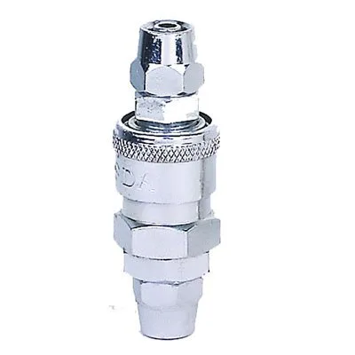
A quick coupling is a hose fitting, and a hose fitting has one job that nothing else on the part can do: it has to make a metal-to-metal seal at the moment a hose is pushed on, and it has to do it inside a second, by hand, without tools, on a dirty bench. Everything else about this component is subordinate to that.
Which is why the shaft and flange here are worth thinking about as a matched pair rather than as two machined features. The shaft carries the load and locates the coupling. The flange carries the reaction torque and lands against the panel or the fitting body. And the seal happens on a conical or serrated seat that sits between them. When a quick coupling weeps, it is almost never because the shaft is undersize. It is because the cone’s angle, the cone’s surface condition, and the plating thickness have drifted apart, and the three of them no longer produce the interference the design assumed.
Chrome plating is a dimensional decision, not a finish
Hard chrome is deposited by building it up atom by atom out of a bath. It is not a coating in the way paint is a coating; it is a structural addition to the part. And that means every dimension on the drawing changes once it is plated.
On a seal cone this is not academic. A cone that seals by interference needs its diameter and angle controlled, and chrome adds material to both the diameter and, at the edge, effectively to the included angle. If the plating specification says 0.025 mm minimum on the cone, the cone grows by 0.025 to 0.05 mm depending on where in the bath’s range the part happened to land. That is a diameter change on a sealing surface, and the seal has to accommodate all of it, every time, including the thinnest and thickest parts the plating process will produce.
The three ways this is handled, and what each one costs:
- Specify the plating before the plating. Say explicitly whether dimensions are before or after plating. This is the single most useful sentence on the drawing and it is missing more often than any other. If dimensions are post-plate, the machining tolerance has to be tightened to leave room for the plating variation.
- Plate the sealing surface less than the rest. A common and effective approach: the shaft body gets standard chrome, the seal cone is either masked or plated to a controlled thinner band. Masking means a plug or a tape, and it means the plating line needs to be told which region is functional.
- Use the plating as the seal. On some designs the plating itself is the sealing element, and then its thickness is the seal parameter. This works, and it makes the plating tolerance a seal tolerance, so it has to be written as one.
Chrome is also hard, and hard has a consequence: it is brittle relative to the steel underneath. A shaft that spends its life under bending load will not fail at the surface, it will fail at the interface where the coating has cracked and the substrate has been work-hardened underneath. On a quick coupling shaft this is rarely a problem, because the loads are low and static. On a part that sees cyclic bending, chrome plus a sharp shoulder radius is a fatigue risk that should be discussed before the print is released, not after the first failure.
Under-chating is the other end of the problem. Chrome adhesion is a bond to a prepared surface, and if the preparation is inadequate the plating lifts. A lifted chrome island on a seal cone is a leak path, and it will also produce a raised surface that damages the mating seal on the first assembly. Adhesion testing on the first article is not a formality on a plated seal part.
The flange, and what it has to resist
The flange on this assembly does two jobs that pull in different directions. It transfers axial load into whatever it is bolted or welded to. And it reacts torque, which arrives at the flange as a moment trying to rotate it about the coupling axis.
Rotating a flange about its own mounting hole pattern is resisted almost entirely by friction at the joint face, and friction is proportional to clamping force. So the bolt specification is not just structural; it is what makes the torque reaction work. A flange with four small screws has a low friction capacity and will slip under sustained torque. The same flange with a proper bolt circle, adequate bolt size, and a defined torque specification has orders of magnitude more resistance.
Three things that belong on a flange drawing because they decide whether it slips:
- The mating face flatness, over the full bolt circle and not just at the bolt holes. A face that is flat at the holes and dished between them concentrates load on two bolts and leaves the others carrying nearly nothing.
- A defined surface finish on the mating face, and a statement of whether it is bare, plated, or coated. A plated face changes the friction coefficient and the corrosion behaviour at the joint, and both change over time.
- Whether the flange is a seat. If another part lands on it and seals against it, then the flange is doing three jobs and the flatness requirement belongs to the seal, not to the structure.
Making it, and the tolerance that actually matters
Bar-fed turning with milled features completed in the same clamping is the right route for a shaft like this, and the phrase “in the same clamping” is the important part. A shaft with a keyway, a flat, and a cross-hole is three setups if it is machined the obvious way, and each setup contributes its own positional error. Concentricity between the seal cone and the mounting diameter, and between the cross-hole and the axis, is held by doing them all from one datum.
What to hold tight, and what can be loose, is worth deciding explicitly rather than applying one tolerance to everything:
- The seal cone’s angle, and its diameter in the post-plated condition. Angle is typically held to a few tenths of a degree because a seal cone does not tolerate a mismatch between its included angle and the mating part’s. This is the tightest dimension on the part and it is the one most often left off the print.
- Concentricity of the cone to the mounting diameter and to the shaft axis, held to something in the region of 0.02 mm depending on size. A cone that is not centred on the axis produces a seal that is thicker on one side, and that unevenness is what the interference is reacting against.
- Thread or spline runout, because a coupling that binds on assembly will damage the cone before it is fully engaged.
- Lengths and diameters that only locate the part, which can hold at +/-0.05 mm or looser without affecting function. This is where tolerance cost is saved.
Bar feeding is worth noting for a reason beyond cycle time: a bar-fed machine holds the stock in a collet against a fixed reference, and every feature machined in that grip inherits the bar’s own axis as its datum. This is why a bar-fed shaft can routinely hold concentricity that would be difficult on a job shop where each part is re-chucked. It also means bar diameter tolerance becomes part of your tolerance stack, and on a diameter-critical part that is worth asking about.
Inspection, and what to actually look at
For a plated sealing part, the inspection plan has to include things that are easy to skip and expensive to discover late.
- Coating thickness by section or by eddy current, at the seal cone specifically, with a stated acceptance range rather than a “per specification” note.
- Adhesion testing on the first article, because plating that lifts is a functional defect that dimensional inspection will not find.
- Cone angle and cone roundness, not just cone diameter. Roundness on a cone that carries interference is what keeps the seal even.
- Concentricity from the CMM, reported against the print rather than against a general capability statement.
- A functional leak or blow-off check if the assembly can be tested, because on this part the seal performance is the specification and everything measured upstream of it is a proxy for it.
Hardened, plated, or just turned to size
Does the seal cone need to be hardened, plated, or simply turned to a controlled dimension? On a low-pressure pneumatic coupling, a hardened ground cone in corrosion-resistant steel will often outlast a chrome-plated carbon steel shaft, and it removes the entire plating-dimension question from the drawing. Chrome is chosen when the part needs wear resistance in service, or when appearance matters, or when the customer has specified it. It is not chosen because it is the default for a shaft that must not rust. On a quick coupling, the seal decides whether the part succeeds, and the seal is a geometry problem before it is a metallurgical one. It is worth establishing which of those you are actually buying before the drawing is frozen, because the two routes have different costs, different lead times, and different failure modes.
The CNC Machining Parts range is the parent for parts like this one; tooling logic, finishing options and tolerance notes for the whole family are gathered on its overview page.
Specifications
| Item | Chrome-Plated Pneumatic Quick Coupling |
|---|---|
| Brand | AUNOV |
| Designing | Quotation reflects the real drawing: tolerances, finish and features are priced as specified. |
| Tooling | Die design and toolmaking stay in house, so the die charge appears as its own quotation line, and ownership is confirmed on the quotation. |
| Samples | The sample you approve becomes the gauge reference for production. |
| Materials | Materials held include carbon steel, 304 / 316 stainless steel, aluminium and brass; mill certificates and heat numbers accompany the first article. |
| Surface finish | Zinc, nickel or chrome plating, anodising, passivation or e-coat; alternatives quoted with the quotation, samples approved in writing. |
| Processing | Bar-fed turning with milled features completed in the same clamping; every stage is logged against your part number. |
| Equipment | 12 CNC turning centres with automatic bar feeders, backed by CNC turning centres and a climate-controlled inspection room. |
| Tolerance | +/-0.01 mm on ground diameters, with GD&T taken from your print; capability is checked on the first article before the run continues. |
| Delivery terms | Freight is quoted to your door in FOB, CIF or DDP terms, payment by T/T or L/C. |
Related Products


Request a Quote for This Part
Send a drawing or sketch — get material advice, tooling cost and a per-piece price within 24 hours (working days).