
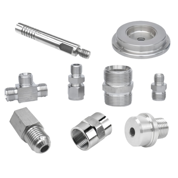
A pipe fitting and a shaft are two products that happen to share a machine
Every mixed order of stainless steel machined pipe fittings and shafts carries an assumption that looks harmless and is not: that because both are round, both are turned on the same lathe, and both are made of stainless steel, they are the same kind of job. They are not. A pipe fitting’s defining attribute is that it seals. A shaft’s defining attribute is that it holds a dimension and a position while something rotates or slides against it. The tolerances that matter are different, the failure modes are different, and the inspection that proves the part is good is different. Reading a combined order as one job is how a supplier ends up inspecting the wrong dimension on both.
AUNOV machines these components on CNC turning centres from 304 and 316 stainless steel, holding machined features to ±0.03 mm, with finishing by passivation, plating or coating per the drawing. This page sets out what actually distinguishes these two product families so that a combined request gets two correct answers rather than one averaged one.
| Attribute | Pipe fitting | Shaft |
|---|---|---|
| Defining requirement | Leak-tight at the rated pressure | Holds diameter, roundness and position |
| Primary controlling dimension | Sealing-face geometry and thread pitch diameter | Bearing diameter and its roundness |
| Typical critical tolerance | Thread pitch diameter, seat angle, face flatness | Diameter to 0.01 mm, runout, straightness |
| Dominant failure mode | Leak at the joint under thermal cycling | Wear, fretting or fatigue at a change of section |
| Verification method | Pressure or leak test plus thread gauging | Micrometer and height gauge, runout on centres |
| Surface requirement | Sealing faces clean and undamaged; internal finish for flow | Bearing surfaces smooth and free of helical marks or scores |
Stainless Steel is not one material, and the fittings care more than the shafts
304 and 316 are quoted almost interchangeably in enquiries and they are not interchangeable here. The difference is molybdenum, roughly 2 to 3 percent in 316, and its effect is to raise resistance to pitting and crevice corrosion in chloride-bearing environments. For a fitting that will hold a stagnant chloride-containing fluid in a crevice at a thread root or under a gasket, that difference is the whole story. A 304 fitting in that service will pit; a 316 fitting will usually not.
The corollary is that the material choice for a fitting should be made from the medium, not from the general expectation of stainless steel being stainless steel. Three questions settle it:
- Is chloride present, and at what concentration and temperature? Pitting resistance falls as temperature rises, and the combination of chloride and elevated temperature is the classic 304 failure.
- Are there crevices? Thread roots, gasket seats and the gaps under a fitting are crevices by design. Crevice corrosion is a harsher test than free exposure and it is where mill certificates stop being reassuring.
- Will the part be welded? Welding sensitizes unstabilized austenitic stainless steel in the heat-affected zone, and 316L rather than 316 is chosen when welding is involved. If the fitting will be welded downstream, say so at the quotation stage.
For shafts, the material conversation shifts. A shaft cares about strength, hardness and wear resistance at the bearing surface, and about whether it will be matched against a stainless steel bearing, a bronze bushing or an elastomer seal. 304 and 316 are both relatively soft and both work-harden aggressively, which affects machining as much as service. If the shaft must resist scoring or fretting at a bearing surface, the options are a different alloy, a surface hardening treatment, or a hardened sleeve — and each of those is a design decision rather than a finish choice.
Stainless Steel machining behaviour that changes what is achievable
Stainless steel is not merely a harder version of carbon steel. It has a low thermal conductivity, which means heat from cutting stays at the tool edge rather than being carried into the chip and the workpiece. It work-hardens rapidly, so a cutting pass that rubs instead of shearing raises the hardness of the surface layer and makes the next pass harder. And it tends to build up an edge on the tool, which is what produces the torn, smeared surface finish that people associate with stainless steel.
The practical consequences for a machined fitting or shaft:
- Cutting speed is lower and feed is higher than for carbon steel. The intent is to get under the work-hardened skin on each pass rather than to skim it. A light finishing pass with a dull tool produces a harder, worse surface than the same pass with a sharp tool at proper feed.
- Rigidity matters more than on other materials. Chatter on stainless steel produces a lobed, uneven surface that will not seal and that will not hold a bearing fit. A long slender shaft is inherently prone to chatter, so a support is often necessary for a shaft whose length exceeds roughly ten times its diameter.
- The surface finish is achievable but not automatic. A 0.4 micrometre Ra on a shaft bearing journal and a 0.8 micrometre Ra on a fitting sealing face are both realistic on our equipment, but they require a specific finishing pass, a specific tool and a stable setup. If a drawing requires fine finish on a feature that is awkward to reach, the cost moves before the tolerance does.
- Galling is the defining risk in service. Stainless Steel threaded joints and stainless steel sliding pairs can seize. Two stainless steel parts of the same grade in a threaded joint that has been tightened and then disassembled is a well-known source of torn threads. The countermeasures are a different grade pairing, a solid-film lubricant such as a nickel-based anti-seize, or a thread insert, and the choice belongs on the drawing.
Threads on a fitting: the tolerance that decides whether it seals
On a tapered pipe thread, the seal is created by the interference between the crests and roots of the male and female threads, aided by a sealant. This means the pitch diameter is the control dimension, not the outside diameter, and the pitch diameter must be checked with a thread gauge rather than measured over the crests. A fitting that measures correctly over its outside diameter can still be loose in assembly, and that failure shows up as a leak, not as a dimensional rejection.
On a straight thread with an O-ring or a bonded seal, the thread’s only job is to generate clamping force, and the seal is made by the compressed elastomer or by the metal-to-metal contact of a cone. Here the critical feature is the seat: its angle, its concentricity with the thread, and its surface condition. A seat that is a fraction of a degree off or that has a score will leak even when the thread is perfect. This is why we gauge both the thread and the seat on a fitting that must seal, and why a customer who specifies only a thread gauge will occasionally receive a fitting that passes the gauge and still leaks.
Three points to write on the drawing for a sealing fitting:
- Thread standard, size and class, stated in full rather than as a nominal size, and whether it is tapered or parallel.
- Seat angle and the diameter at which the seat angle begins, since an angle without a location reference can be cut anywhere.
- Surface condition on the seat, expressed as a roughness value or as a prohibition on circumferential marks.
Shafts: the dimensions that actually control behaviour
A shaft drawing usually carries a length, one or more diameters, and a tolerance on each diameter. That set of dimensions is not sufficient to describe a shaft, and the missing ones are the ones that cause problems in service.
- Roundness of the bearing journal. Diameter alone does not control roundness. A journal can measure correct on a two-point micrometer and still be two or three lobes out of round from a turning centre’s error. A three-lobed journal in a plain bearing will fail to form a hydrodynamic film correctly and will wear unevenly. Where a journal runs in a precision bearing or bushing, specify roundness or, equivalently, specify measurement on a roundness tester rather than with a micrometer.
- Runout relative to the bearing axis, not to the end faces. A shaft’s functional axis is established by the surfaces that locate it, which are its bearing journals or its centres. End faces are convenient to work to and are frequently not the right reference. A ten micrometre runout on the bearing journals relative to each other is a real problem; the same runout relative to a chamfer is irrelevant.
- Straightness, and whether it is verifiable. On a long shaft, straightness is often the attribute that decides whether the assembly works, and it is often unspecified. A shaft that must pass through two bearings separated by a distance needs a straightness that is a fraction of the bearing clearance over that span. If the drawing does not state it, the shop will deliver whatever the process produces, which may be perfectly acceptable and may not.
- Surface finish on the sliding or sealing surfaces. A seal lip running on a turned surface with a helical feed mark will pump fluid along the mark, producing a leak that is invisible in the shop. Specifying a plunge-ground or roller-burnished finish, or explicitly prohibiting continuous helical marks, prevents it.
- Fillet radii and undercuts at every diameter change. A sharp shoulder on a rotating shaft is a fatigue crack initiation site. A generous fillet removes the concentration; an undercut allows the mating part to seat against a face rather than against a radius. Which one is correct depends on what is mounted there, and the drawing should show it.
Inspection: two parts, two proof methods
The verification plan follows from the definitions above. For fittings, the proof is a functional one: thread gauging plus a pressure or leak test on a sample basis, plus seat angle measurement and a visual check at magnification for circumferential defects on the seat. For shafts, the proof is dimensional and geometric: diameter at multiple positions along the journal to detect taper and lobing, roundness on the critical journal, runout between journals on centres, straightness over the functional length, and surface finish measurement on the sliding surfaces. A shaft that is proved only by a diameter measurement has not been proved at all.
Where the quantity justifies it, we build a functional gauge or a mating fixture for the fitting and check every piece against it. This catches the class of error where each individual dimension is within tolerance but the combination is not — for instance a thread that is at the loose end of its pitch diameter combined with a seat that is at the shallow end of its cone depth. Neither dimension alone would justify a rejection; the pair would.
Finishing and passivation
Stainless Steel parts usually leave the machine with a surface that is metallurgically contaminated by the tooling. Free iron and embedded particles from cutting tools and from a previous carbon-steel job on the same machine will rust on a stainless steel surface, and the resulting stain is often misdiagnosed as a failure of the stainless steel itself. Passivation, typically a nitric or citric acid treatment, removes the free iron and allows a clean passive layer to form.
Which parts need it, and what they need instead of it, depends on the application:
- Fittings for a corrosive or hygienic service. Passivate, and specify that the passivation covers all internal passages. A fitting that is passivated externally only will pit from the inside.
- Shafts running in a bearing or a seal. Passivation is generally safe and beneficial, but the acid treatment must not be allowed to leave a smeared or dulled surface on a fine bearing journal. Where a journal has been finished to 0.4 micrometre Ra, the finishing operation is placed after passivation.
- Threaded parts. Passivation does not change the pitch diameter appreciably, which is one of its advantages over plating. Plating, by contrast, adds a layer that must be accounted for on the pitch diameter, and it should be specified as a pre-plate allowance.
- Parts that will be welded. Passivation before welding is wasted on the weld area, which will be disturbed by the heat. Order the sequence so that the final passivation follows the final thermal operation.
What to include in a request for fitting and shaft work
- The medium, its chloride content, its temperature range and whether it is stagnant in crevices.
- Whether any part will be welded downstream, which may change the grade to an L version.
- For fittings: the thread standard in full, the seat angle with a location reference, and the acceptance method for leak tightness.
- For shafts: roundness and runout requirements with the datum axis identified, straightness over the functional length, and the finish requirement on bearing and seal surfaces.
- The mating parts, at least by description, because the fit is a joint property and not a part property.
- The finishing sequence, especially where passivation must follow final machining or where plating must precede a thread gauge check.
- Whether the order contains both fittings and shafts, so that the quotation and the inspection plan can be built as two distinct parts rather than one.
The L grade costs little and prevents a welded fitting failing in service
Can you supply 316L instead of 316 for the fittings?
Yes, and we would recommend it wherever the part will be welded or where the service temperature is elevated in a chloride environment. The cost difference is small compared with a field failure.
The shaft diameter is in tolerance but the bearing is tight. What causes that?
Almost always roundness or straightness rather than diameter. A two-point micrometer cannot detect a three-lobed journal, and a slightly bowed shaft will bind in two bearings even when every local diameter is correct. Ask for the roundness and runout data on the journals.
Do the fittings need to be pressure tested one by one?
For critical service, yes, and we will quote it as a separate operation. For general industrial service, sample testing combined with full dimensional and thread gauging is usually the right balance. Tell us the consequence of a leak in the field and we will propose the level of proof that matches it.
How do I stop stainless steel fittings seizing on assembly?
Specify an assembly lubricant, or specify a dissimilar pairing such as a stainless steel body with a nickel-plated or bronze component where the design permits. Alternatively, use a thread insert in the female part. The key is to decide this at the drawing stage, since the thread form and the plating allowance depend on it.
Can a worn shaft be repaired rather than replaced?
It can be built up and remachined, or a scuffed journal can be metal sprayed and ground, but both routes require that the base material is sound and that the heat input does not distort the shaft. For most of the parts in this family, replacement is the more predictable option and often the cheaper one at low quantity.
CNC Machining Parts is the parent range for parts like this one; the overview page gathers the tooling logic, finishing options and tolerance notes that apply across the family.
Specifications
| Item | Stainless Steel CNC Machined Pipe Fittings and Shafts |
|---|---|
| Brand | AUNOV |
| Designing | Share your print, or send a part to be measured, our engineers reply with a manufacturability assessment and pricing. |
| Tooling | Tooling designed and cut in house, with your part number on the tool record. |
| Samples | Sample parts arrive with dimensional data plus material certs. |
| Materials | 304 / 316 stainless steel is the primary stock for this part, alongside carbon steel (SPCC / DC01), aluminium, brass and copper, and the grade is fixed at the drawing review. |
| Surface finish | Plating, e-coat, powder coating, anodising or passivation as the drawing calls out, as called out on your print. |
| Processing | Staged deep drawing, with in-line annealing where the draw ratio requires, then pierced and CNC-machined in house. |
| Equipment | 5-250 T mechanical presses plus 250-500 T hydraulic presses, in-house CNC cells and a temperature-controlled inspection room. |
| Tolerance | +/-0.1 mm on as-drawn features, with machined features to +/-0.03 mm. |
| Delivery terms | FOB is standard; DDP offered for EU and US, T/T or L/C, with D/P for repeat business, scheduled call-offs welcome. |
Related Products
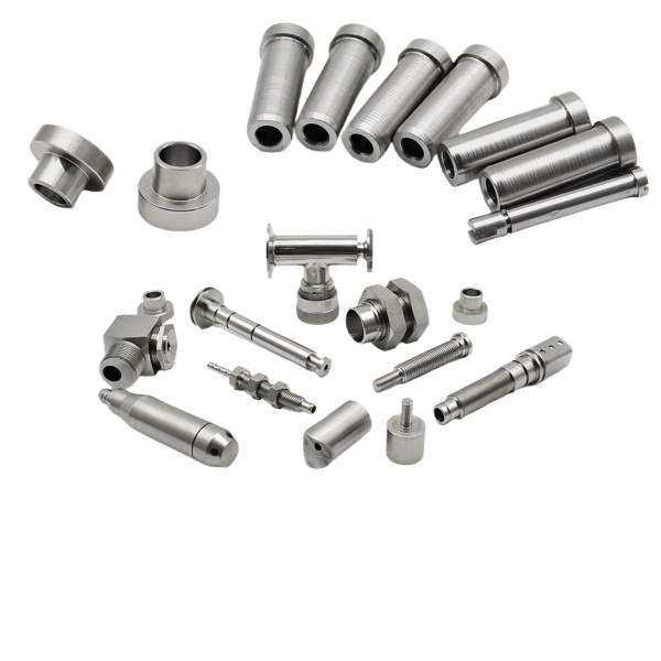


Request a Quote for This Part
Send a drawing or sketch — get material advice, tooling cost and a per-piece price within 24 hours (working days).