
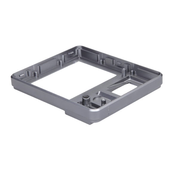
A rectangular frame’s torsional stiffness comes from its corners, not its sides
An aluminum rectangular mounting frame—four sides forming a rectangle that carries a component or panel—is torsionally only as good as its corner joints. Under a twisting load (one diagonal up, the other down), the frame deforms by rotating about its corners: a pin-jointed frame (fastened only by bolts through clearance holes) behaves almost as a mechanism, while a welded or pinned-and-bolted corner transforms the frame into a torsion tube.
Quantitatively, the difference is a factor of 10–50 in torsional stiffness between bolted-corner and fully-fixed-corner frames of the same section. We build rectangular frames to three stiffness tiers: (1) bolted corners with fitted dowels at each corner—two ground dowel pins per corner, reamed holes, bolted clamp—giving a torsional stiffness within 20–30 % of welded; (2) TIG-welded corners with full penetration, for maximum stiffness at the cost of HAZ-softened local strength; (3) bolted corners with corner gussets (triangular plates bolted or riveted across the inside corner), a field-serviceable compromise. The drawing’s tolerance on frame diagonal-to-diagonal difference (the direct measure of squareness) tells us which tier the design needs: 0.5 mm+ per meter is tier 3; 0.1 mm per meter demands tier 1 or 2.
Frame squareness is measured diagonally, not by comparing sides
The frame’s functional squareness—whether the mounted panel or component sits true—is captured by comparing the two diagonal measurements across the frame. Equal sides do not guarantee square (a parallelogram has equal opposite sides); equal diagonals do. We measure both diagonals with a calibrated tape or, for precision frames, on a CMM, and the acceptance criterion is a diagonal difference under 0.2 mm for standard frames, under 0.05 mm for precision mounting frames.
Squareness correction for bolted frames happens at assembly: the frame is clamped to a granite surface table, diagonals measured, and the corners’ dowel/bolt sequence tightened in the order that pulls the long diagonal closed (diagonals tell you which corners to close first). We do this correction once at our assembly bench and ship the frame square; a frame that leaves square and stays square until it’s bolted down stays square in service.
Mounting hole patterns on the frame’s sides must reference one master datum, not each side’s own edge
A frame carries mounting holes on multiple sides—component bolts on top, attachment holes on the bottom, cable ports on a side. If each side’s holes are machined referencing that side’s own edges, the accumulation of side-to-side tolerances lands on the customer’s assembly: the top’s hole pattern lands out of position relative to the bottom’s by the sum of every side’s positioning error.
We machine all hole patterns in one fixture referencing a single master datum: the frame’s bottom face and one datum corner. On a four-axis machining center, the frame is clamped once and every side’s features are machined in indexed setups that re-reference the same master. The result: top-to-bottom hole pattern alignment within 0.05 mm, versus 0.2–0.4 mm for per-side referencing. For customers bolting two matched frames face-to-face, this datum discipline is the difference between bolts dropping in and an afternoon of reaming.
Anodize and the frame’s joint faces: mask what must conduct or bear
The frame’s finish (typically clear or black Type II anodize) is applied after all machining, but three categories of surfaces must be masked: (1) any electrical-grounding surfaces (anodize insulates); (2) fitted surfaces—dowel holes and their surrounding lands, where the anodize’s 8–10 µm build changes fits that were cut to size; (3) welding lands if any second-operation welding or bonding will happen at the customer (anodize must be removed before welding, and removal on an assembled frame is miserable).
We plan masking into the route: silicone plugs for dowel holes, masking tape for grounding pads, and a drawing note on every masked zone. Post-anodize, every masked dowel hole is gauge-verified (the plug gauges the same class it did before coating)—a masked hole should gauge identically, and if it doesn’t, the mask leaked and the hole gets re-worked before assembly.
How we verify rectangular mounting frames before shipping
- Squareness: Diagonal-to-diagonal difference, on the CMM or with calibrated diagonal measurement: 0.2 mm standard, 0.05 mm precision.
- Flatness of mounting faces: The frame’s top and bottom mounting lands (granite + indicator): 0.05 mm standard—these faces carry the component and the frame’s own attachment.
- Hole patterns: CMM verification of all patterns against the master datum on the first article; production frames get gauge-pin span checks on the critical patterns.
- Corner integrity: Bolted corners—dowel pins gauge-checked, bolts torqued to spec and marked; welded corners—visual for undercut, dye penetrant on structural welds per drawing.
- Assembly trial (precision frames): The frame’s mating component (or a gauge plate with the mating hole pattern) is trial-fitted: bolts drop, no forcing, diagonal re-checked after bolting. A frame that distorts when its component bolts down is corrected (shim, re-dowel, or re-square) before shipping.
CNC Machining Parts is the parent range for parts like this one; the overview page gathers the tooling logic, finishing options and tolerance notes that apply across the family.
Flatness across a large frame
A rectangular mounting frame is only as good as its flatness where the components bolt down, and that flatness is hard to hold on a large thin section that wants to twist as it is machined free. We rough, relieve stress, and finish cut the faces in sequence, fixturing on the back so the clamps do not bow the frame, and we measure it after it has settled, not while it is still held. The boss heights that the components reference are held to that flat plane, because a frame that reads flat under clamp and warps on the bench is the defect a line finds only after the first assembly will not seat.
Boss height variation for stacked assemblies
When components stack on the frame, the boss heights decide the gaps, so we hold each boss to the frame plane within a tight band and we reference them all to that one plane rather than to each other. A stack built on bosses that vary part to part wobbles, and the variation is invisible until the top component will not seat. We machine the bosses in one setup from the frame datum so they share a truth, and we check the spread across a lot because a single good sample hides a process that drifts.
Specifications
| Item | Aluminum CNC Machined Rectangular Mounting Frame |
|---|---|
| Brand | AUNOV |
| Designing | A drawing file or a physical sample starts the review, the quotation comes back with a manufacturability review attached. |
| Tooling | Dies engineered and produced in our own toolroom, with your part number on the tool record. |
| Samples | Samples for approval come with dimensional data and material certs. |
| Materials | Aluminium is the primary stock for this part, alongside carbon steel (SPCC / DC01), 304 / 316 stainless steel, brass and copper, with grade selection confirmed at drawing review. |
| Surface finish | Finish options: plating, e-coat, powder coating, anodising or passivation, per your print. |
| Processing | Staged deep drawing, with in-line annealing where the draw ratio requires, then pierced and machined in house. |
| Equipment | Press capacity from 5 to 500 T across mechanical and hydraulic lines, CNC turning centres, climate-controlled CMM room. |
| Tolerance | As-drawn tolerance +/-0.1 mm, +/-0.03 mm on machined surfaces. |
| Delivery terms | Standard terms FOB, DDP offered to EU and US, T/T or L/C, D/P on repeat business, call-off schedules and blanket orders supported. |
Related Products


Request a Quote for This Part
Send a drawing or sketch — get material advice, tooling cost and a per-piece price within 24 hours (working days).