
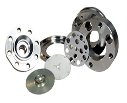
A compression tube fitting has no threads on the tube side, and that one design decision creates an entire category of requirements that threaded fittings do not have. A compression fitting seals by squeezing the tube – either by deforming it or by compressing an elastomer onto it – and because the seal is made by mechanical force on the tube itself, the fitting and the tube become a matched pair that neither supplier controls.
That is the whole story on this part. Everything interesting follows from it, including the tube’s wall thickness, the fitting’s design limits, and the reason compression fittings are specified with a tube rather than with a size.
Three compression designs, and they are not interchangeable
The ferrule type, which bites the tube
A conical or diamond ferrule is driven axially into the tube’s end and is pulled down against the body as the nut is tightened. The ferrule deforms and bites into the tube wall, and it is the ferrule’s back and front faces that seal against the body’s seat and the tube’s end.
- The seal is the ferrule’s conical face against the body. The ferrule has to deform enough to bite but not so much that it cuts through the tube wall.
- The tube’s wall thickness is a hard constraint. A ferrule designed for a thin-wall tube will cut through a thick-wall one, and a thick-wall tube in a thin-wall fitting’s ferrule will not be gripped. This is the single most common reason a compression fitting leaks, and it is because the ferrule’s design assumes a wall thickness range.
- The assembly is a controlled process – the nut is tightened to a defined torque in a defined number of turns, or the fitting is a mechanical-compression type with a visible witness. On a hand-assembled field fitting, that control is absent and the leak rate will be worse.
The V-profile or bite-type, which grips harder
A simplified single-piece ferrule with a V-shaped profile that grips the tube in two or four places. It handles a wider wall range and needs less assembly torque, which is its advantage in field service.
The elastomer-sealed or push-fit type, which grips an outer diameter
An elastomer ring or a collet grips the tube’s outside. Here the tube’s wall thickness is not the constraint – the tube’s outside diameter is – and the fitting can be connected and disconnected repeatedly without damaging the tube.
- This is the design to specify if the tube will be disconnected repeatedly or if a field installation is involved, and it is the wrong choice if the connection must be vibration-proof or if the tube could be pulled out of the fitting.
- The pull-out strength is limited and it should be stated as a requirement wherever a push-fit is used on a line that could be pulled.
The tube, which is the fitting’s real specification
This is the point that should appear at the top of any compression fitting’s specification, and it is the one that is most often missing: the fitting is specified with a tube, not with a size.
- Outside diameter and wall thickness, both with tolerances. A compression fitting specified only by outside diameter is half-specified. The wall thickness tolerance determines whether the ferrule will grip or will cut through.
- The tube’s material and temper, because the ferrule bites a soft copper differently from a hard stainless steel, and a stainless steel tube’s work-hardening behaviour matters when it is being bitten.
- Whether the tube’s ends are prepared – square cut, deburred, and to what finish. This is the most common cause of a leaking compression joint that is otherwise correctly assembled, because a squared or burred tube end will not sit flat against the ferrule’s front face and the seal is a face seal as well as a bite.
- Whether the tube can be damaged by assembly and whether that is acceptable. A compression fitting permanently deforms a thin-wall tube. If the tube is required to remain undisturbed – because it is part of an instrument or a sensor – then the fitting type has to be chosen accordingly, and a mechanical-compression or a push-fit design is the answer.
The flow path and the pressure drop, which is a real specification
A compression fitting’s internal geometry is a small bore with a shoulder in it – the ferrule’s seat – and that shoulder is a restriction and a turbulence generator.
- The internal bore and the ferrule’s bore, and which of them is smaller. On most designs the ferrule’s front bore is the restriction, and it is smaller than the body’s bore, so the fitting’s capacity is set by the ferrule.
- Where the fitting is in a line where pressure drop matters – a cooling line, a sampling line, a fuel line – the drop should be stated and measured at a stated flow.
- On a high-flow or a gas application, the fitting’s internal geometry also has to avoid dead legs, because a compression fitting is assembled in place and its internal volume is essentially inaccessible afterwards.
Threads, and where they are allowed
A compression fitting has a thread – on the end that connects to the port. It is a metal-to-metal or elastomer-sealed thread, and it has its own requirements, which are the familiar ones.
- The thread’s seal method. If it is a tapered pipe thread, the fitting is a metal-to-metal seal on that end and the relaxation under thermal cycling applies. If it is a parallel thread with a bonded seal or an O-ring, the tolerance is wider and the assembly torque is less critical.
- Plating a compression fitting’s thread changes the fit, and the plating will flake at the thread’s roots. On a stainless steel fitting, passivation rather than plating is the right answer and it costs nothing.
- And the specific point on this page: the thread’s finish and the ferrule’s finish are independent. A fitting can be a perfectly good compression fitting with a badly finished thread, and the thread is the end that is inspected, so a bad assembly there looks like a fitting fault when it is not.
A compression fitting is judged on what it grips
Stock covers carbon steel, 304 and 316 stainless steel, aluminium and brass, with special grades sourced to the drawing when volumes justify. On a compression fitting the material decision is more consequential than on a plain fitting for one specific reason: the ferrule has to be able to deform.
- Brass is the traditional material and it is still the best answer for most applications, for a specific reason: the ferrule needs to be ductile enough to deform and grip without cracking, and to be strong enough to hold. Brass does both. Its limitation is dezincification and its galling against steel fittings.
- Stainless Steel 316L is the answer where the fluid is a corrosive process, a cooling medium, or anything with chlorides – and it is standard on compression fittings for that reason. But a stainless steel ferrule is harder and less ductile than a brass one, which means the design has to account for a ferrule that bites harder and can crack at its back face, and it means the ferrule’s material is not freely substitutable. 316L on the body and a harder alloy on the ferrule is a normal and intentional pairing.
- Carbon steel is used where the fluid is benign, with a plating, and the ferrule is a harder steel so it grips the tube. Its limitation is corrosion of the body and of the ferrule – and a corroding ferrule on a copper tube will produce a galvanic corrosion problem on the tube.
- Aluminium is used for lightweight lines and it is workable, but an aluminium ferrule on a copper or a steel tube is a galvanic couple in a wet connection, and aluminium’s low strength limits the ferrule’s grip force.
A plated ferrule changes the friction the drawing never mentioned
Plating, coating or polishing to suit the drawing, with finish thickness and adhesion checked on the first article. Three specific cases.
- The ferrule’s working surfaces should not be coated in a way that changes their geometry or their friction. A plated ferrule will change the fitting’s torque characteristics and it will flake into the fluid path, which on a compression fitting is a contamination problem as well as a fitting problem.
- On stainless steel, passivation is the answer and plating is not. Passivation leaves the geometry alone and restores the corrosion resistance that machining removed.
- The body’s sealing face – where the ferrule seals against it – should be unmasked and preferably polished, because that face’s finish determines how evenly the ferrule seats and therefore how evenly the fitting seals.
The ferrule’s own geometry decides whether a compression fitting grips
+/-0.01 mm on ground diameters, GD&T from the print, critical dimensions carrying CMM data with the shipment. On a compression fitting the flagged dimensions are the ones that determine whether it grips and whether it seals.
- The ferrule’s geometry – its taper or V-profile, its diameter, and its length – held, because the ferrule is what does the work and its dimensions determine both the grip and the seat’s seal. These are the tightest dimensions on the part and they are normally held to a much tighter band than the body’s general tolerance.
- The body’s ferrule seat – its diameter, its taper, and its position relative to the ferrule. A body that is correct and a ferrule that is correct but do not seat correctly together will leak, and this is why ferrule and body are usually matched at assembly.
- The thread, per its class, gauged.
- The bore and the flow path’s dimensions, for the pressure drop.
- The hex or the wrench flats, as a fit to the wrench, with the corner condition.
- The seating face that the tube end lands on, and its perpendicularity, since the tube end’s face seal depends on it.
- General dimensions at a general band.
Leak testing over a range of torques is what a compression fitting needs
- A functional leak test on every part, at the specified assembly torque and, where the fitting is field-assembled, over a range of torques. On a sealing component this is the only test that tests the specification, and on a compression fitting it is especially valuable because it tests the ferrule and the seat together.
- Ferrule and body seating verified together – the ferrule’s seating face against the body’s seat, visually against a standard, on a sample.
- The ferrule’s taper or profile, and its diameter, measured.
- Thread gauging, and the wrench flats as a wrench fit.
- The ferrule’s grip verification where the design is a mechanical-compression type with a witness – the witness mark’s presence is the acceptance criterion and it should be inspected on every part.
- Critical dimensions carrying CMM data with the shipment, and batch records filed so a repeat order starts from approved data – which on a compression fitting matters because the ferrule and the body are a matched set.
The tube, its wall thickness, and how often it is remade
What is the tube – its material, its outside diameter, its wall thickness and its tolerance – and is this connection made on a line and left, or made and remade? The tube’s wall tolerance is the part that decides whether the fitting grips or whether it cuts through, and it is the one number that is almost always missing. The second half of the question decides the fitting type entirely: a connection that will be made once and left can use a ferrule design at full assembly torque, and a connection that will be made repeatedly in the field needs either a mechanical-compression design with a witness or a push-fit design that does not damage the tube. And there is a third question worth asking at the same time – whether the tube has to remain undistorted after assembly, because a compression fitting that deforms the tube is not acceptable if the tube is part of an instrument, a sensor’s capillary, or anything that depends on its cross-section. Three short answers, and they determine the fitting type, the ferrule material, and whether the assembly torque is a specification or a free parameter.
CNC Machining Parts is the range this part sits under; the overview page pulls together the tooling logic, finishing options and tolerance notes that apply across the family.
Specifications
| Item | Stainless Steel Flange Plates and Discs Assortment |
|---|---|
| Brand | AUNOV |
| Designing | Quotation follows the print, not a catalogue – DFM notes are returned before any tooling is cut; changes are priced before they are made. |
| Tooling | Our toolroom covers die design, wire-cut EDM and maintenance, so tooling lead time stays under our control, and ownership is confirmed on the quotation. |
| Samples | Sample parts are measured and reported before submission, so the approved first article becomes the gauge reference, and the signed sample is kept for future reorders. |
| Materials | Stock covers carbon steel (SPCC / DC01), 304 / 316 stainless steel, aluminium and brass; special grades are sourced to the drawing when volumes justify. |
| Surface finish | Plating, coating or polishing to suit the drawing; finish thickness and adhesion checked on the first article. |
| Processing | Turn-mill machining, critical diameters finished in one setup; batch records are filed so a repeat order starts from approved data. |
| Equipment | 12 CNC turning centres with automatic bar feeders, with CNC turning centres for secondary operations and CMM inspection. |
| Tolerance | +/-0.01 mm on ground diameters, with GD&T taken from your print; critical dimensions carry CMM data with the shipment. |
| Delivery terms | FOB Ningbo or Shanghai, payment by T/T or L/C, quoted in USD or EUR; price breaks tie to annual volume. |
Related Products


Request a Quote for This Part
Send a drawing or sketch — get material advice, tooling cost and a per-piece price within 24 hours (working days).