
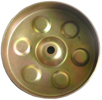
The yoke: half the motor’s torque lives in this ring of steel
Permanent magnets push flux; the wiper motor yoke is what brings it home. Sitting inside the drawn housing wall or forming the wall itself, the yoke closes the magnetic circuit from magnet, across the air gap, through the armature teeth, and back around. When a motor designer wants more torque per amp, the yoke is one of the first places to look – and one of the most misunderstood, because the behaviours that matter (permeability, saturation, dimensional consistency of the flux path) behave nothing like the mechanical properties a drawing usually specifies.
Saturation: the ceiling nobody sees
Low-carbon steel carries flux comfortably until about 1.5-1.6 tesla, then saturates – permeability collapses, and further magnet strength buys almost nothing. A yoke wall too thin for its flux load saturates at the corners and opposite the magnet poles first, and the motor loses torque that its magnets were perfectly capable of producing. This is why yoke wall thickness is a magnetic decision, not a mechanical one: a 1.0 mm wall that passes every structural check can still be magnetically starved in a six-pole motor with strong ferrites. We ask for the magnet grade and pole count at RFQ precisely so the wall thickness gets checked against flux density before tooling, using the simple rule that the yoke’s flux-carrying section must match the total magnet flux per pole without exceeding ~1.4 T locally.
Material: what actually works
- Low-carbon steel (DC01-class) – the default. Cheap, magnetic, draws well. Its carbon content is low enough that magnetic ageing is negligible at wiper operating temperatures.
- 1.4016 ferritic stainless steel – the corrosion route. Holds a respectable permeability, draws slightly stiffer than DC01, and skips plating. Its magnetic properties vary more between mills, so we qualify the source when a customer specifies it for the yoke specifically.
- 300-series stainless steel – do not. Austenitic, effectively non-magnetic, work-hardens further with drawing. Every so often a drawing arrives specifying 304 “for corrosion” on a yoke, and the resulting motor quietly loses 20-30% of its torque. We flag it before quoting – it is the single most valuable free review we perform.
Drawn yoke versus laminated stack
Bigger motors use laminated stator stacks to cut eddy losses, and a natural question is why wiper yokes are solid drawn shells. The answer is frequency: a wiper motor’s armature sees commutation frequencies in the hundreds of hertz at most, where eddy losses in a solid yoke are a rounding error next to the friction and copper losses. The drawn yoke also brings structural benefits a stack cannot – it is the pressure vessel that holds magnets against centrifugal and assembly loads, and its dimensional roundness sets the air gap’s uniformity. Laminations enter the picture only if the design migrates to BLDC with electronic commutation, where switching frequencies climb and the yoke conversation changes entirely.
Dimensional consistency as a magnetic property
The air gap between magnet surface and armature is set by three parts, and the yoke owns one: the inner surface the magnets bond to. A yoke wall that varies 0.05 mm around its circumference varies the air gap by the same amount, and torque ripple follows the variation. This moves a forming requirement – roundness and wall uniformity – into the magnetic domain. Our control: restrike calibration to hold roundness within 0.05 mm at the magnet land, wall-thickness mapping on first articles, and a magnet-land surface finish spec (the bonding adhesive needs it anyway). Customers who measure air-gap variation at motor build consistently find it tracks the yoke’s, which is why we chart it.
Yoke wall thickness changes the air gap
The yoke drawing with magnet-land diameter and width, the magnet grade and pole count (so we can sanity-check wall thickness against flux), material family, and volume. If the yoke is integral with the housing rather than a separate ring, add the housing drawing – the two share a draw plan. First articles in three to four weeks after die approval, with wall-thickness mapping included as standard.
Motors test 15% low on torque – could the yoke be the cause?
Our motors test 15% low on torque – could the yoke be the cause?
If the yoke wall is saturating or the air gap is uneven, yes. Send us the yokes and the magnet spec; we map wall thickness and roundness and run a flux-path sanity calculation, and the answer usually shows up in the thickness map.
Can you make the yoke and housing as one drawn part?
Often – the housing wall doubles as the yoke in many wiper designs. It concentrates tolerances into one draw and deletes a press-fit operation at your line; the trade is that the material must satisfy both the magnetic and corrosion specs simultaneously, which usually lands on DC01 with plating or 1.4016.
Does drawing direction affect magnetism?
Slightly – rolling direction changes permeability by a few percent in low-carbon steel. It is real but small; we mention it because customers chasing the last percent of torque sometimes hear about it from a lamination vendor and worry it is bigger than it is.
Automotive Motor Components is the parent range for parts like this one; the overview page gathers the tooling logic, finishing options and tolerance notes that apply across the family.
Specifications
| Item | Wiper motor yoke |
|---|---|
| Brand | AUNOV |
| Designing | Made to your 2D/3D drawings (PDF, DWG, STEP, IGS) – DFM notes are returned before any tooling is cut; changes are priced before they are made. |
| Tooling | Dies, fixtures and gauges are made in our own toolroom, so no tooling step is outsourced, and ownership is confirmed on the quotation. |
| Samples | Pre-production samples come with a full inspection report, so the sample is retained as the master, and production starts only after your written sign-off. |
| Materials | Carbon steel (SPCC / DC01), 304 / 316 stainless steel, aluminium, brass and copper – the grade is matched to the duty of this yoke. |
| Surface finish | Zinc or nickel plating for corrosion, plus powder coating or electrophoresis on housings; laser etching on request. |
| Processing | Coil blanking, progressive drawing through 3-5 stages with anneals between, trim and pierce, then deburr and finish. |
| Equipment | 5-250 T mechanical presses and 250-500 T hydraulic presses, in-line annealing furnace, CNC turning for secondary work. |
| Tolerance | +/-0.03 mm on machined features, +/-0.1 mm on formed ones, with first-article inspection report. |
| Delivery terms | FOB, with DDP offered for EU and US addresses, payment by T/T, L/C at sight or D/P; sea or air freight is quoted to your door. |
Related Products


Request a Quote for This Part
Send a drawing or sketch — get material advice, tooling cost and a per-piece price within 24 hours (working days).