
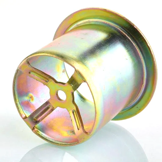
A housing is judged by what bolts to it
Draw the shell, trim the flange – and the wiper motor housing is still not a part until its interfaces close. In practice the housing is the middle of a fit stack: end-bell bolted to the flange, sintered bushing pressed into the bore, armature shaft running in that bushing, gear housing spigotted onto the opposite face, seal riding on the flange edge. Every tolerance in that chain was chosen somewhere, and when wiper motors come back with noise or wear complaints, the root cause is more often a tolerance mismatch across interfaces than a forming defect inside the shell. This page is about engineering those interfaces deliberately.
The fit stack, face by face
- Bushing bore. The armature’s only radial support. We hold the bore to H7 after any coining or burnishing, and concentric to the housing OD within 0.05 mm – because the customer presses the bushing with 0.02-0.06 mm interference, and an off-centre bore turns a uniform press into a lopsided one that wipes the bushing’s oil film on one side.
- Flange gasket face. Flatness within 0.15 mm over the diameter. Tighter is possible by restrike calibration but rarely specified for good reason – the gasket itself absorbs 0.1 mm of waviness, and chasing 0.05 mm flatness buys nothing once the seal is rubber.
- Gear-housing spigot (where fitted). Some wiper designs spigot the gear housing directly to the drawn shell. That diameter needs a true positional callout to the bushing bore – typically 0.08 mm – because the gear train’s backlash lives in that alignment.
- Mounting ears. Bolt holes in drawn ears locate the whole motor in the vehicle. Their pattern tolerance is loose (±0.2 mm is fine), but the ear faces must be parallel to the flange within about 0.5 mm or the motor mounts pre-stressed.
Why we press for a tolerance review before tooling
The most valuable hour in a wiper housing programme is the one spent striking out over-tolerances. Drawings inherited from a machining-era design often carry ±0.02 mm walls and 0.01 mm flatness calls that a drawn part meets only by luck and sorting. We do not simply accept them – we propose print revisions that move tolerance budget to the faces that function: the bore, the flange, the spigot. The arithmetic is persuasive: loosening three cosmetic tolerances by a class funds the tighter bore concentricity that actually protects the motor, with no net cost increase. Customers who take the review get parts that are easier to make correctly; customers who do not get parts sorted, which is a polite way of paying for scrap twice.
Press-fit engineering for the bushing
The bushing joint deserves its own paragraph because it is the interface that fails. Interference too low and the bushing spins under load, machining the bore; too high and the housing wall necks or cracks at the bore edge. The workable band for a sintered bronze bushing in a 1.0-1.2 mm steel wall is narrow – roughly 0.02-0.05 mm – which is why we coin or burnish the bore rather than leave it as-drawn: the as-drawn bore carries a thickness variation that converts a paper interference into a real one somewhere along the bore. Coining sets the diameter and ironing the wall smooths the variation; the combination holds the press-fit band across the whole batch.
Assembly-side practicalities
Three details that cost nothing at the press and save minutes at the customer’s line. Ear holes pierced with a chamfer side down so bolts start clean. A flange witness line – a faint 0.1 mm step – that makes gasket orientation foolproof. And deburred cable-exit edges, because a cut grommet is a warranty photo waiting to happen. None of these appear on a drawing’s tolerance block, and all of them come up in the first month of line trials.
The bore is one route to that whine
Send the drawing with the fit stack identified: which diameter takes the bushing, which face the end-bell, which pattern locates the vehicle. Add annual volume and the motor’s noise spec if one exists. We return a tolerance review first – free, because it saves both sides rework – then a die plan and first articles in three to four weeks after approval.
Motors whine at high speed – could it be the housing?
Our motor whines at high speed – could it be the housing?
Possibly, through the bushing bore’s eccentricity modulating shaft alignment. Send us the suspect housings or the motor returns; we measure bore position on our CMM against the print and usually have an answer within a week.
Can you supply housings with the bushing already pressed?
Yes – we press, gauge, and staking-secure bushings as a value-added step, and it removes the interface risk from your line entirely. The premium is small because the press operation is fully offline to the drawing press.
Do you need our end-bell drawing?
It helps, especially for the spigot joint and bolt pattern – interfaces are judged in pairs, and we would rather see both halves than guess the gap.
This part belongs to our Automotive Motor Components range. The automotive motor components pages collect the process notes, common materials and inspection points behind every product in the family.
Specifications
| Item | Wiper motor housing |
|---|---|
| Brand | AUNOV |
| Designing | Driven by your drawing or a physical sample – a manufacturability review comes back with the quotation; the approved drawing is kept as the controlled master. |
| Tooling | Progressive and drawing dies are designed and built in house, so the die charge appears as its own quotation line, and maintenance is tracked against the part number. |
| Samples | First-article samples ship with a dimensional report and material certificate, so any deviation is corrected at sample stage, and production starts only after your written sign-off. |
| Materials | Carbon steel, 304 / 316 stainless steel, aluminium and brass are held in stock; the drawing review fixes the final grade. |
| Surface finish | Adhesion comes from phosphating, followed by powder coating, e-coating or zinc plating; visible faces get chrome or nickel. |
| Processing | Deep drawing runs from coil or blank; in-process annealing keeps wall thinning even, and trim, pierce, form and finish follow. |
| Equipment | The press floor pairs 5-250 T mechanical with 250-500 T hydraulic presses; an in-line annealing furnace sits on line and CNC turning covers secondary work. |
| Tolerance | +/-0.15 mm typical on formed parts, +/-0.3 mm on large covers; the die decides the achievable band. |
| Delivery terms | FOB, CIF or DDP per Incoterms 2020, payment by T/T or L/C, quoted in USD or EUR; call-off schedules are supported. |
Related Products



Request a Quote for This Part
Send a drawing or sketch — get material advice, tooling cost and a per-piece price within 24 hours (working days).