
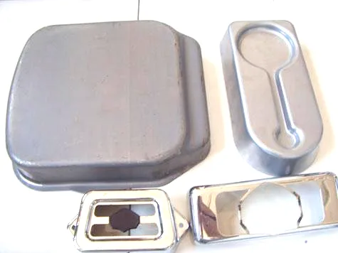
A box is stiff because it is closed, and that is the whole design
A deep drawn box is the simplest closed shape in stamping, and it is the one where a single property – stiffness – depends on the fact that the section is closed rather than on how much steel is in it. Open a rectangular section along one side and its stiffness falls by an order of magnitude for the same material and the same wall. That is why a deep drawn box resists bending and torsion so much better than a channel or an angle of the same gauge, and why it is worth paying for the draw when a box will do the job.
We blank from coil and draw progressively, with coining on the final station where the print calls for it, on 5-250 T mechanical and 250-500 T hydraulic presses with annealing ovens on site, CNC turning centres for secondary operations, and CMM inspection. Formed features are held to +/-0.05 mm with capability data on critical dimensions, and capability is checked on the first article before the run continues. Carbon steel in SPCC and DC01 grades, 304 and 316 stainless steel, aluminium and brass are held on site, and mill certificates and heat numbers accompany the first article.
Corner geometry: where a box is won or lost
Every corner in a drawn box does three jobs at once, and they conflict. A corner must:
- Flow. Material has to travel around it during the draw. This wants a large radius, because a tight radius is where the material stretches most and where it thins most.
- Stiffen. A corner is a natural stiffener, and a tight square corner is much better at resisting a change of shape than a generously radiused one.
- Be manufacturable. The die has to make the corner, and a very tight square corner in a deep draw is where tooling wears fastest and where cracking starts.
The resolution is a small radius combined with a relief or a reducing feature, rather than a large radius or a sharp corner. The radius itself carries the flow, and the stiffness comes from the section not collapsing rather than from the corner geometry. On a box that must resist denting – a cover, an enclosure, a fascia – the design control that matters most is not the corner but the flat panel’s resistance to a point load, which is governed by wall thickness and by whether the panel can dish.
Drawing a box is a two-direction problem
This is the technical point that distinguishes a box from a cup. A cup is drawn in one direction: material moves toward the punch. A box requires material to move in two directions – it becomes deeper and it changes footprint – and that has two consequences:
- Corner thinning is unavoidable and predictable. In a square or rectangular cup, the corners are the last material to be drawn and they take the most stretching. The wall at a corner will be significantly thinner than the wall in the middle of a face, often by enough to matter. This is not a defect and it should not be inspected as one; it is geometry. Where a corner needs a defined wall thickness – because it carries a load, seals, or brazes – the design either adds a corner relief or specifies the corner as a thinned region.
- The draw ratio in the depth direction is the limiting one. A box that is deep relative to its footprint reaches the practical limit of a single draw sooner than a shallow one, which is why deep boxes need multiple stages and interstage annealing.
Sidewall flow is also uneven. In a rectangular box the material in the middle of a long face travels further than the material at the corners, so a long thin box has a draw distribution that is hard on the middle of the long faces. Square-ish footprints draw much more uniformly than long rectangles, and where a long rectangular box is required, the process plan needs to account for it.
Walls, welds and where a box is opened
A closed box has one problem that an open bracket does not: it is a pressure-tight volume by accident. If it is a cover, an enclosure or a housing, someone eventually asks whether it needs to be vented, and if it does not get vented, a sealed box changes pressure with temperature and can bow its panels.
- Venting. A closed metal box under a temperature change develops a small pressure differential. Over time this can be enough to permanently deform a panel, or enough to leak a joint that would otherwise hold. A vent hole, a loose cover joint, or a deliberately non-sealed assembly solves it, and it is worth deciding at design stage rather than discovering it as a bowed panel.
- Welded or brazed versions. Where a box is assembled from a drawn body and a separate panel, the joint is the weak point. The weld seam’s heat input distorts the box – panels bow because welding pulls them – and controlling this needs a defined fixture, a defined sequence, and often a straightening operation afterwards. Where the box must stay flat, a brazed or a bonded joint can be preferable because it moves far less.
- Where the box must be joined to something. A drawn box with a mounting flange formed on it, or with tapped holes in its base, changes the draw plan. Forming a flange on a box rim is a common operation; forming features into a box’s base after drawing is a secondary operation with its own tolerance.
Cosmetics on a box: the largest visible surface on the part
Where a box is visible, the finish requirements tighten considerably and the sequence matters. Plating, powder coating, anodising or polishing are all available per the print, with alternatives quoted alongside and samples approved in writing.
- Plating. Uniform and durable, with good dimensional control on flat panels. Corners and radius transitions build up more coating than the flats, and a visible box will show this as a slight tonal difference at the corners. Where appearance is critical, this is often acceptable on mild radii and not acceptable on tight ones.
- Powder coating. Excellent on a box – thick, hard, and it hides a lot of the underlying drawing variation – but it is a thick film that adds to every dimension and requires masking of any threaded or sealing feature. Textured and fine-texture powders are common on enclosures for grip and for appearance.
- Anodising on aluminium, where the box is decorative or cosmetic. Requires the design to be in an anodisable alloy, which is a material decision rather than a finishing decision.
- Polishing or brushing. On a stainless steel box, a directional finish has to be chosen and its direction specified, because a drawing does not carry a lay direction by default and two shops will produce two different appearances.
The dimension point applies throughout: the drawing must state whether dimensions are before or after finishing. On a box where panels must be flat, a coating film thick enough to matter is a real tolerance issue and not a detail.
Flatness of a drawn panel, and why it is achievable
A large flat panel in a drawn box is the feature most likely to be out of specification, because panels dish and bow under residual stress from the draw. Three controls, in order of cost:
- Design the panels to carry load without dishing. A panel with a supporting flange or a hemmed edge is much stiffer than a plain flat panel of the same thickness.
- Coining. The final station on this route, where the print calls for it, presses the panel to a controlled flatness at the cost of some tool life. This is the standard method on a box that has a flatness requirement, and it is why the processing description calls coining out.
- Handle carefully afterwards. A coined panel that gets bent in handling is out again, and on a large box the handling is often worse than on a small part. Restrictive packaging is not a nicety on this product.
Odd walls, threads and tolerances get feasibility-checked before tooling
Made to your 2D or 3D drawings in PDF, DWG, STEP or IGS, with unusual walls, threads or tolerances feasibility-checked first and changes priced before they are made. The die is dedicated to your part and maintained on a recorded schedule. Sample parts are measured and reported before submission, so any deviation is corrected at sample stage and later batches are gauged back to the signed sample.
Six things worth resolving on a deep drawn box before tooling, in rough order of how often they change the design:
- What loads the box sees, and therefore which walls need to be thicker. Corner thinning means a uniform wall specification is not what the draw delivers, so the thickness requirement should be given where the thickness matters.
- Whether the box must be vented, or whether it is intentionally sealed and must be able to hold that.
- What the panels must achieve – flatness, dent resistance, or nothing in particular. Each leads to a different design and a different finishing route.
- Where it seals, if it seals, and whether those surfaces are masked from coating.
- How it is assembled – welded, brazed, screwed, riveted, or a snap fit – because that decides whether the box can be deformed slightly in assembly.
- Which feature is the datum, and what the panel’s flatness is measured against.
Mill certificates and heat numbers accompany the first article, capability data is available on critical dimensions, and capability is checked on the first article before the run continues – which on a box is usually the panel flatness and the corner wall, the two things a drawing cannot fully guarantee and a first article can demonstrate.
Draw ratio, wall thinning, radii and trim — the design decisions behind a part like this are worked through with numbers in our deep drawn covers guide, and the Precision Deep Drawn Parts pages collect the rest of the family.
Specifications
| Item | Deep drawn box |
|---|---|
| Brand | AUNOV |
| Designing | Made to your 2D/3D drawings (PDF, DWG, STEP, IGS) – unusual walls, threads or tolerances are feasibility-checked first; changes are priced before they are made. |
| Tooling | The die is dedicated to your part and maintained on a recorded schedule. |
| Samples | Sample parts are measured and reported before submission, so any deviation is corrected at sample stage, and later batches are gauged back to the signed sample. |
| Materials | Carbon steel (SPCC / DC01), 304 / 316 stainless steel, aluminium and brass are held on site; mill certificates and heat numbers accompany the first article. |
| Surface finish | Plating, powder coating, anodising or polishing, per the print; alternatives quoted with the quotation, samples approved in writing. |
| Processing | Coil blanking and progressive drawing, coining on the final station where the print calls for it; first articles verify the whole flow before the run is released. |
| Equipment | Press shop running 5-250 T mechanical and 250-500 T hydraulic presses, annealing ovens on site, with CNC turning centres for secondary operations and CMM inspection. |
| Tolerance | +/-0.05 mm on formed features, with capability data on critical dimensions; capability is checked on the first article before the run continues. |
| Delivery terms | FOB, CIF or DDP per Incoterms 2020, payment by T/T or L/C, quoted in USD or EUR; price breaks tie to annual volume. |
Frequently Asked Questions
Why choose a deep drawn box instead of a welded or folded one?
A deep drawn box is a closed section, and a closed section is an order of magnitude stiffer in bending and torsion than a channel or angle of the same gauge, because the stiffness comes from the shape being closed, not from more material. Drawing it in one piece also removes the weld seam that a fabricated box would have, so there is no joint to fail.
Where is a deep drawn box won or lost?
At the corners. The corner radius and the wall thinning through the corner control whether the box draws cleanly or tears and wrinkles, so the corner geometry is the first thing reviewed at quotation. A corner that is too tight for the material simply will not draw, and one that is too open wastes the stiffness the box was chosen for.
Which materials are used for a deep drawn box?
Carbon steel in SPCC and DC01 grades, 304 and 316 stainless steel, aluminium and brass are all held on site, with the grade matched to the duty and mill certificates and heat numbers accompanying the first article. The choice follows the environment the box sees, not a default habit.
What tolerance holds the walls and flange of a drawn box?
Formed features are held to a few hundredths of a millimetre with capability data on the critical dimensions, and the flatness of the drawn panels is achievable because the draw sets the reference faces. The band is proved on the CMM at first article before the run continues.
Related Products


Request a Quote for This Part
Send a drawing or sketch — get material advice, tooling cost and a per-piece price within 24 hours (working days).