
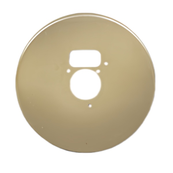
A faceplate is a flatness part, and drawing it flat is the hard part
A deep drawn faceplate is sold as a flat panel with a rim, but the flatness is the product and the drawing is the easy half. A faceplate is a very shallow draw, a large flat face with a small returning flange, and the failure mode is never a crack, it is a dish. The flat face springs from the residual stress of the draw and the trim, and if the process does not control it, the plate rocks on the surface plate and the gasket it is meant to seat never makes contact all the way round.
We hold faceplate flatness to a tight band, typically 0.1 to 0.2 mm total across the face, and we win it with a restrike that re-seats the face in a flat die after the first draw has released its spring. A faceplate that is drawn and trimmed but not restruck will dish by an amount that depends on the blank holder force and the trim relief, and that amount is not predictable enough to ship. The restrike is the operation that turns a drawn disc into a flat plate.
The flatness also depends on the flange being balanced. A flange that is wider on one side pulls the face into a tilt, so we trim the flange concentric to the face datum and check the face on the plate before any coating, because paint will not hide a dish, it will only seal it under a wave.
Cutouts near the edge turn the faceplate into a spring after trimming
The feature that most often ruins a faceplate flatness is a cutout near the edge. A cutout removes the material that was holding the local stress balanced, and after trimming the plate releases that stress by curling toward the cutout. A slot 10 mm from the edge of a 2 mm plate will lift the edge by a millimetre or more once the trim frees it, and the faceplate that looked flat before piercing is a spring afterward.
We anticipate this by piercing after the restrike where the flatness is already set, or by adding a local stiffening feature near the cutout so the edge cannot lift. Where the cutout is structural, we keep it a controlled distance from the edge, usually more than the plate thickness plus a margin, and we verify the edge lift on the first article with the plate on the surface plate and a feeler at the cutout. A faceplate that lifts at a cutout is a faceplate that will not seat its gasket along that edge.
The ordering matters: if we pierce before the restrike, the restrike flattens the curl but the cutout then sits in a plate that has already been disturbed, and the hole position drifts. If we restrike then pierce, the hole is placed in a flat plate and stays put. We restrike then pierce, which is the subject of a later section.
- Keep cutouts more than the plate thickness plus margin from the edge to limit edge lift.
- Restrike for flatness before piercing so the hole sits in a flat plate.
- Verify edge lift at the cutout on the surface plate on the first article.
- Add a local stiffener near a structural cutout rather than accept the curl.
Powder coat adds thickness to every edge, and the cutouts shrink
A painted faceplate is almost always powder coated, and powder coat is not a film, it is a layer, typically 60 to 120 micrometres per side once cured. On a plate that is 2 mm thick, that is a measurable fraction of the edge, and on a cutout that is 5 mm wide it is a fifth of the opening. The cutouts shrink, the edges grow, and a clearance that was fine as drawn becomes an interference after coating unless the coating thickness was designed in.
We open the cutouts and the edges by the full coating thickness plus the clearance the assembly needs, and we verify the coated opening, not the bare opening, because the mating part meets the paint, not the steel. A faceplate whose cutouts were sized on the bare edge will bind on the harness or the switch it was meant to clear, and the bind is invisible until install. The same logic applies to any boss or standoff on the faceplate: the coating adds to its height and its bore, and both are sized pre-coat.
For the flat face the coating is less critical dimensionally, but it still adds to the standoff from the mating surface, so the gasket compression has to be specified against the coated thickness, not the bare plate, or the seal is over- or under-compressed after painting.
Why we pierce before forming, or the cutout distorts out of position
There are two valid orders for a faceplate with cutouts, and the choice depends on whether the cutout is near a formed feature. For cutouts in the flat face, we pierce after the restrike, as above, so the hole sits in a flat, stable plate. For cutouts that must align with a formed rim or a bent flange, we pierce before the final form, located to the flat blank, so the form carries the hole to its final position without the hole wandering during the draw.
The failure of getting this wrong is a cutout that is the right size but in the wrong place, because a hole pierced in a flat blank and then drawn with the plate moves with the metal, sometimes by millimetres, and a hole that was dimensioned from a drawn feature ends up off that feature. We therefore locate cutouts from the blank datum when they are pre-pierced, and from the formed datum when they are post-pierced, and we state which on the first article so the inspection knows what it is checking against.
The blank holder force during any form near a cutout is also tuned so the cutout edge does not distort as the wall moves, because a cutout near a deforming region will oval if the hold-down is uneven, and an oval hole is a hole that will not pass the switch or the grommet.
Paint adhesion on a drawn edge depends on the radius you left
A faceplate is painted for appearance and for corrosion, and paint adhesion on a drawn edge is where both are won or lost. A sharp drawn edge has high local curvature and a thin, stressed coating that chips at the first handling; a generous edge radius holds a uniform coat and resists impact. We hold the drawn edge radius at 1 to 2 times the plate thickness on the visible edges, and we pretreat the aluminium or steel so the coat keys, because a faceplate whose paint flakes at the rim looks failed even when the plate is sound.
The pretreatment also has to reach the cutout edges, which are bare steel or aluminium after piercing and are the first places corrosion starts if the coat is thin there. We verify coating thickness at the cutout edges and at the drawn rim with a magnetic or eddy gauge, not just on the flat face, because the edges are exactly where the coat is thinnest and the failure begins.
For a faceplate that seats a gasket, the coating at the seal line has to be uniform too, because an uneven coat there means an uneven seal, and a seal that leaks at a thin spot of paint is a leak that gets blamed on the gasket.
How we verify a painted faceplate that has to seat a gasket blind
A faceplate is often installed where the seal cannot be seen, so the verification has to guarantee the seat blind. The first article carries the checks below and production is audited against it.
- Face flatness is measured on the surface plate and held to the band on the drawing, checked before coating.
- Edge lift at every cutout is felt and measured after piercing and after coating.
- Coated cutout and edge dimensions are verified against the assembly clearance, not the bare-edge drawing.
- Coating thickness is gauged at the drawn rim and at the cutout edges, not only on the flat face.
- Cutout position is checked against the correct datum, blank or formed, as the process used.
- Material and heat are traced to the mill certificate so the pretreatment matches the alloy.
Send the drawing or a sample faceplate, and the review returns the coating thickness we will design in, the restrike for flatness, and the cutout clearance after paint, so the plate that ships seats its gasket the first time.
Our deep drawn covers guide puts numbers to the design decisions behind a part like this — draw ratio, wall thinning, radii and trim; the Precision Deep Drawn Parts pages collect the rest of the family.
Specifications
| Item | Painted Steel Deep Drawn Faceplate with Cutouts |
|---|---|
| Brand | AUNOV |
| Designing | Send drawings, or send a sample to be measured, DFM feedback is returned with the quote. |
| Tooling | Tooling designed and cut in house, stored under your part number. |
| Samples | Sample parts arrive with dimensional data and material certification. |
| Materials | Carbon steel (SPCC / DC01) leads the stock list for this part, alongside 304 / 316 stainless steel, aluminium, brass and copper, with the final grade confirmed at the drawing review. |
| Surface finish | Surface treatment per the drawing: plating, e-coat, powder coating, anodising, passivation, per the drawing. |
| Processing | Staged deep drawing with in-line annealing where needed, with piercing and finish machining under the same roof. |
| Equipment | On the press side, 5-250 T mechanical and 250-500 T hydraulic; CNC turning centres and a climate-controlled CMM room complete the floor. |
| Tolerance | +/-0.1 mm on as-drawn features, machined features held to +/-0.03 mm. |
| Delivery terms | FOB as standard, DDP available for EU and US destinations, T/T or L/C, with D/P for repeat business, call-off scheduling supported. |
Frequently Asked Questions
What makes a deep drawn faceplate difficult when it is such a shallow draw?
Flatness is the product and the drawing is the easy half. The failure mode is never a crack, it is a dish: the large flat face springs from the residual stress of the draw and the trim, and a plate that rocks on the surface plate never seats its gasket all the way round.
Why is there a restrike after the first draw?
A faceplate that is drawn and trimmed but not restruck will dish by an amount that depends on the blank holder force and the trim relief, and that amount is not predictable enough to ship. The restrike re-seats the face in a flat die once the first draw has released its spring, which is the operation that turns a drawn disc into a flat plate.
How do cutouts change the flatness problem?
A row of cutouts near the edge removes the material that was holding the panel in tension, so the remaining ligament behaves like a spring once it is trimmed free. Cutout position therefore has to be reviewed against the edge distance and the trim relief together rather than laid out from the cosmetic drawing alone.
Should the cutouts be pierced before or after forming?
The right answer depends on what has to stay true: piercing before forming risks pulling the feature out of position during the draw, while piercing after means the trimmed edge condition decides where the cutout can sit without tearing into it. We settle it per feature during manufacturability review, against which tolerance governs fit, rather than applying one house rule to every cutout.
Related Products



Request a Quote for This Part
Send a drawing or sketch — get material advice, tooling cost and a per-piece price within 24 hours (working days).