
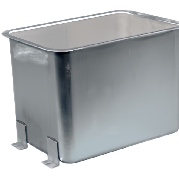
Mounting feet are formed features, and they fight the tank roundness
A tank with mounting feet is two parts in one: a rotationally symmetric shell, and a set of discrete feet that break that symmetry. The feet are not added afterward in most of our builds; they are formed from the same blank, raised or pierced as the shell is drawn, and that is exactly where the trouble starts. Every foot is a local pull on the wall, and if the feet are not balanced around the circumference, the shell twists as it is drawn and the roundness you paid for in the die walks out the door.
We keep the feet symmetric in the tooling so the pulls cancel, and we locate the shell for any post-form from the same datum the draw used, so a foot that is pierced or coined after drawing lands where the bolt circle expects it. A foot added off a warped locator is a foot that misses the hole pattern by the locator error, which on a tank that has to bolt to a skid is the difference between a clean install and a file in the field.
The other fight is between the foot and the wall. A foot formed by thinning the local wall is a weak foot and a thin spot in the pressure boundary; a foot formed by raising extra material is a foot that holds the bolt load without denting the shell. We form from extra material, and we section the first article at a foot to prove the wall under it is still at nominal.
316L draws harder than it looks, so the blank diameter grows
The tanks we build for wet or food service are 316L, and 316L is a stiffer draw than its appearance suggests. Its work-hardening exponent is higher than 304, so the first draw demands more force and the limiting draw ratio sits a little lower, which means the blank has to be larger relative to the finished diameter to feed the wall without tearing. A blank sized from 304 habits will split a 316L corner, and the split shows up on the first article, which is the cheap place for it to show.
We start the 316L blank one step larger in diameter than the equivalent 304 part and draw it through an extra reduction where the depth demands it, with in-line annealing because 316L work-hardens into its own failure if you push two draws without softening. The press assignment follows the force: the deep 316L shell runs where the ram force is controlled, not on a fast mechanical press that slams the corner before the metal has decided to flow.
The reward for the larger blank and the extra stage is a shell that keeps its corrosion grade through forming, because 316L’s advantage is its chemistry, and you do not want to thin it to the point that the surface finish or the local composition variation lets pitting start at a draw mark.
Feet placement is a bolt-circle problem long before it is a weld problem
Before anyone worries about welding a foot, they should worry about where the foot sits on the bolt circle, because foot position is a position tolerance, not a size. A foot that is 1 mm off its bolt-circle angle will not line up with the skid holes, and no weld quality makes up for a foot in the wrong place. We dimension the feet as position to the tank axis and to each other, and we verify the bolt circle on the first article with a co-ordinate check rather than by measuring each foot from an edge.
The circle also has to be flat. A tank that bolts down on feet of unequal height rocks, and the rock loads the shell and the seals. We hold foot height to a tight band across all feet, typically within 0.1 mm of each other, and we check it with the tank resting on a surface plate so the feet, not the shell, carry the measurement. A foot that stands proud by 0.2 mm is a foot that takes the load alone and dents.
When the feet are welded rather than formed, the same position discipline applies, with the added rule that the weld must not move the foot we already located, which is the subject of the next section.
- Dimension feet as position to the axis and to each other, not as size from an edge.
- Hold foot height within 0.1 mm across all feet so the tank does not rock.
- Verify the bolt circle on the CMM, not by individual edge measurements.
- Form feet from extra material so the wall under them stays at nominal.
A stainless steel tank holds a fluid, so the bottom radius is a stress concentrator
A tank is a pressure or at least a hydrostatic boundary, and the bottom corner radius where the wall meets the base is the stress concentrator the rest of the shell is not. Under a fluid column the bottom radius carries the bending where the straight wall turns into the base, and a tight radius there is a tight stress line that fatigue finds first. We hold the bottom radius generous, typically 4 to 6 times the wall thickness on these tanks, and we section the first article to confirm the wall through the radius is still at nominal, because a thin bottom corner is a thin pressure boundary.
The failure mode is not an instant burst; it is a slow lap-seam or corner leak after cycles of fill and drain, where the concentrator works the material until a microcrack opens. We avoid it by drawing the radius rather than machining it, because a drawn radius has continuous grain flow through the corner, whereas a machined one cuts the grain and exposes fresh surface to the fluid. For 316L in particular, continuous grain at the corner is what keeps the pitting from starting where the stress is highest.
We also specify the internal finish at the bottom radius, because a drawn surface there is smoother than a machined one and gives corrosion less to hold onto. The choice of radius is therefore a corrosion decision as much as a forming one.
Welding feet to a drawn shell without moving the roundness you paid for
Where feet are welded rather than formed, the weld is the operation most likely to undo the roundness and flatness the drawing already achieved. A fillet weld around a foot shrinks as it cools and pulls the shell locally, and if the fixture does not hold the shell against that pull, the roundness you measured on the first article is gone by the time the tank cools. We weld feet in a fixture that locates the shell on its own axis and restrains the wall, and we sequence the welds so the pulls cancel rather than accumulate.
The weld also has to respect the 316L. A contaminated or overheated weld loses the corrosion resistance the tank was bought for, so we weld with the grade-appropriate filler, keep the heat input controlled, and passivate or clean the heat-tint band afterward. A weld that looks sound but lost its passivity at the toe is a weld that pits first, which on a tank is the worst kind of hidden defect.
After welding we re-check the roundness and the foot bolt circle, because the weld is the one step that can move both, and the customer’s install depends on them being where the drawing says after, not before, the feet went on.
How we verify a feet-mounted tank for flatness on the floor
A tank with feet is judged standing on a surface plate, because that is how it lives. The first article is measured on the plate and in the CMM, and production is audited against it.
- Foot height is compared across all feet with the tank resting on a surface plate, held within 0.1 mm so it does not rock.
- The foot bolt circle is checked as position to the axis on the CMM, not by edge dimensions.
- Bottom corner radius is sectioned on the first article and the wall through it confirmed at nominal.
- Shell roundness is re-measured after any welding, because the weld can move it.
- Weld is inspected for contamination and heat tint, and passivated where the grade requires it.
- Material and heat are traced to the 316L mill certificate so the corrosion grade is documented.
Send the drawing or a sample tank, and the review returns the blank size for the 316L draw, the foot position stack, and the bottom radius we will hold, so the tank that ships bolts down true.
Drawing, machining and welding each win on different geometries; the guide to deep drawn covers works through those boundaries, and the full Precision Deep Drawn Parts range is reachable from the overview page.
Specifications
| Item | Stainless Steel Deep Drawn Tank with Mounting Feet |
|---|---|
| Brand | AUNOV |
| Designing | Send drawings, or send a sample to be measured, the quotation comes back with a manufacturability review attached. |
| Tooling | Every die designed and built in our toolroom, with your part number on the tool record. |
| Samples | Samples for approval come with a dimensional report and material certification. |
| Materials | Stock for this part leads with 304 / 316 stainless steel, alongside carbon steel (SPCC / DC01), aluminium, brass and copper, with grade selection confirmed at drawing review. |
| Surface finish | Plating, e-coat, powder coating, anodising or passivation as the drawing calls out, per your print. |
| Processing | Staged deep drawing, with in-line annealing where the draw ratio requires, pierced and finish-machined on the same floor. |
| Equipment | Mechanical presses 5-250 T and hydraulic presses 250-500 T, in-house CNC cells and a temperature-controlled inspection room. |
| Tolerance | +/-0.1 mm on as-drawn features, with machined features to +/-0.03 mm. |
| Delivery terms | Prices FOB, with DDP for EU and US on request, T/T or L/C, D/P on repeat business, blanket orders and call-offs supported. |
Frequently Asked Questions
Why do formed feet make roundness harder to hold than on a plain tank?
Every foot is a local pull on the wall, and feet that are not balanced around the circumference twist the shell as it draws, so the roundness paid for in the die walks out during forming. On a plain rotational shell there is no such asymmetry to fight, which is why a feeted tank has to be treated as two problems sharing one blank.
Why does the choice of 316L change the blank rather than only the tooling?
The alloy work-hardens faster and springs back differently, so drawing it behaves like a stiffer version of the same geometry and the developed blank has to grow to suit. Treating it as a tooling-only change usually surfaces as a short flange or a split late in the first draw, both of which are blank decisions discovered too late.
Is locating a foot a welding problem or a bolt-circle problem?
It is a bolt-circle problem long before it becomes a weld problem. We keep the feet symmetric in the tooling so the pulls cancel, and any post-form operation is located from the same datum the draw used, because a foot added off a warped locator misses the hole pattern by the locator error.
Where does a feet-mounted tank actually fail in service?
At the bottom radius, which is a stress concentrator on a vessel holding fluid, and at the feet-to-floor interface where warped roundness turns into an uneven footprint. Both are addressed by controlling roundness through the draw rather than by correcting it afterwards.
Related Products


Request a Quote for This Part
Send a drawing or sketch — get material advice, tooling cost and a per-piece price within 24 hours (working days).