
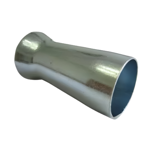
The Steel Deep Drawn Tapered Cone Sleeve Zinc Plated is a conical part, and cones are a special case in deep drawing: unlike a cylinder, a cone’s wall is mostly unsupported during the stroke, which changes the failure modes from “too much tension” to “wrinkles first, then anything.” This page explains how we draw tapered sleeves, where the dimensions sit on a cone, and what zinc plating has to prove on a sloped surface before the batch ships.
The unsupported-wall problem: drawing a cone without wrinkles
In a cylindrical draw, the punch supports the forming wall almost from the first millimetre of stroke. In a conical draw, the punch tip touches the blank at a point and the wall between tip and die remains free until late in the stroke. That free annulus is a thin sheet in compression – it has nowhere to transfer hoop stress, so it buckles into wrinkles, and once a wrinkle forms it irons into the wall as a permanent defect or cracks in the next stage. Wrinkle control is therefore the entire engineering content of a conical draw.
- Blank-holder pressure is the first control: high enough to suppress the buckling wave, low enough that the flange can still feed. The window is narrow on cones and we find it at first article with sensors on the press, then archive the settings against the part number.
- Stage geometry is the second: we do not draw straight to the final taper. Early stages carry nearly cylindrical walls that support themselves, and the taper is developed across later passes – each stage converting more parallel wall into sloped wall, with the draw beads controlling the feed so the free zone never grows past what the material tolerates.
- The die’s transition radii are cut generously on cone work because the metal’s direction change at the cone flank concentrates there; a tight radius here is the classic origin of circumferential cracking on the small end.
Depth beyond roughly twice the small-end diameter means staged drawing with in-line annealing – routine here with hydraulic presses up to 500 T, but planned in the stage table and quoted openly, because the stage count is the tooling cost.
Blank sizing and small-end control on a tapered sleeve
A cone’s blank is sized by surface area, and the sizing arithmetic is unforgiving: too small a blank and the cone’s small end thins below wall spec; too large and the surplus material has to wrinkle or thicken somewhere. Between those outcomes sits the target – a blank whose area equals the cone’s developed area plus trim, and whose position in the die is controlled so the surplus lands in the trim, not in the wall.
- The small end is the cone’s tightest zone and its gaugeable anchor: we hold the small-end diameter as the named dimension on the as-drawn part, to the ±0.1 mm class of drawn surfaces, and where the small end must locate a part, it is machined afterwards to ±0.03 mm.
- The taper itself is set by the final die and punch pair; because it is generated by tool geometry rather than material flow, it is the most repeatable feature on the part – the inspection question is not whether the taper repeats, but whether the diameter stations along it sit where the drawing says.
- We gauge the cone at multiple stations – small end, mid-flank, large end – because a cone can pass at both ends and be wrong in the middle if an anneal state drifted mid-batch; station data catches what end-only checks hide.
Zinc on a sloped wall: coverage where the current does not want to go
Zinc plating on a tapered sleeve has a geometry problem and a service problem. The geometry problem is recess throwing power: a cone’s interior is a funnel, and the deposit runs thin toward the small end where the anode cannot see the surface. The service problem is that tapered sleeves usually serve outdoors or under-hood, where the finish is not cosmetic – it is the part’s entire corrosion budget.
- We rack tapered sleeves so the small end faces the anode field and use conforming anodes where the depth-to-diameter ratio starves the recess; the first article includes thickness verification at the small end specifically, because that is where an unmanaged bath falls short.
- Deposit targets follow the duty: a trivalent or alkaline zinc layer in the 5-15 µm class with a conversion layer, specified on the drawing so the salt-spray class is a contractual number rather than a brochure claim.
- Hydrogen management applies to these SPCC / DC01 shells as it does to all our plated steel: bake-out after plating is recorded, because a tapered sleeve is often clamped into a boss and the clamping load is exactly where embrittled steel speaks up.
- Where the cone’s surface will slide or seal, we say at review whether zinc is even the right answer – sometimes a machined stainless steel small end or a different finish outperforms a plated cone, and the cheapest place to have that conversation is before the die is cut.
Angle-to-angle contact: how a cone actually mates
A tapered sleeve almost always mates by taper – into a matching bore, over a spigot, or against a seat – and a taper pair is a tolerance amplifier. Two cones at the nominal angle mate along their whole length; two cones 0.2° apart in angle mate at one end only, and which end depends on the sign of the error. The drawing review therefore asks where the fit is required to bind, and the process plan biases the taper so the bind lands where the designer wants it.
- Where the taper is a seal seat, the mid-flank stations are the governing dimensions and we gauge them as named sections, not as a single diameter at the convenient end.
- Where the taper is a press that wedges, the small-end diameter and the angle govern, and the first article reports both so the assembly’s retention is a calculated value rather than a hope.
- Where the sleeve seats against a flat, the large end’s squareness to the cone axis becomes the named measurement – a cone can be dimensionally perfect and still rock on its seat if the end is out of square by a fraction of a degree.
Straightness, flare and the handling of thin-wall cones
Conical sleeves are thin-wall parts by nature – the taper means there is no thick section anywhere – and thin-wall cones deform in handling with a willingness that surprises buyers used to cylinders. The damage modes are edge flare at the large end, dings on the flank and ovalisation of the small end, and every one of them is a fit defect that no diameter call-out catches. The countermeasures are packaging discipline and end protection, planned as part of the process rather than improvised at the dock.
- Large ends get rigid protection or stacking nests so the flare never starts; a flared cone will not enter its mating bore and the damage is invisible until assembly.
- Flank dings are screened by the same station gauging that watches the taper – a station reading out of position tells us the wall moved before it tells us why.
- Batches are packed to the drawing’s handling class, and where the customer’s line unstacks parts automatically, the packing format is designed around their feeder rather than our convenience.
How we verify a tapered sleeve against its drawing
The sequence below is fixed per part number, from first article onward.
- CMM first article: diameter stations along the taper – small end, mid-flank, large end – plus large-end squareness to axis and overall height, in the climate-controlled room against your print.
- Angle verification: the taper angle reported as a measured value so the mating pair’s bind position is known, with end-only checks explicitly rejected as insufficient.
- Wall and form: thickness at the small end and mid-flank thin sections, plus concentricity of the cone to the large end where the print locates off it.
- Zinc evidence: deposit thickness at the small-end recess per the drawing minimum, conversion layer class, adhesion from the qualification batch, and bake-out records.
- Lot integrity: mill certificate per heat, the archived stage and press settings, and the signed first article every production batch is gauged back to under ISO 9001.
Our deep drawn covers guide puts numbers to the design decisions behind a part like this — draw ratio, wall thinning, radii and trim; the Precision Deep Drawn Parts pages collect the rest of the family.
Specifications
| Item | Steel Deep Drawn Tapered Cone Sleeve Zinc Plated |
|---|---|
| Brand | AUNOV |
| Designing | Share your print, or send a part to be measured, our engineers reply with a manufacturability assessment and pricing. |
| Tooling | Tooling designed and cut in house, held under your part number. |
| Samples | Approval samples ship with a full dimensional report and mill certificate. |
| Materials | Stock for this part leads with carbon steel (SPCC / DC01), alongside 304 / 316 stainless steel, aluminium, brass and copper, and the grade is fixed at the drawing review. |
| Surface finish | Finish options: plating, e-coat, powder coating, anodising or passivation, selected against the drawing requirement. |
| Processing | Multi-stage drawing, annealed in line where wall thinning calls for it, pierced and machined on the same floor. |
| Equipment | Press capacity from 5 to 500 T across mechanical and hydraulic lines, in-house CNC cells and a temperature-controlled inspection room. |
| Tolerance | +/-0.1 mm as-drawn, machined features held to +/-0.03 mm. |
| Delivery terms | FOB standard, DDP offered for EU and US, T/T and L/C; D/P on repeat accounts, call-off schedules and blanket orders supported. |
Frequently Asked Questions
Why does a cone wrinkle when a cylinder of the same depth does not?
In a cylindrical draw the punch supports the forming wall almost from the first millimetre of stroke. In a conical draw the punch tip touches the blank at a point and the annulus between tip and die stays free until late in the stroke, and that free ring has nowhere to pass its hoop stress, so it buckles.
Once a wrinkle forms, can it be removed?
No, and this is why wrinkle control is the entire engineering content of a conical draw. The wrinkle either irons into the wall as a permanent defect or cracks at the next stage, so prevention at the blank holder stage is the only reliable route.
When does a tapered sleeve need staged drawing with annealing?
Depth beyond roughly twice the small-end diameter. That threshold moves the part from a single operation into a stage table with in-line annealing, which is routine on hydraulic presses up to 500 T, and it belongs in the quoted plan because the stage count is the tooling cost.
Why is plating more difficult on a sloped wall?
Current distribution follows geometry, so coverage thins where the current does not want to go, and a tapered wall presents a continuously changing angle to the bath. Plating the sleeve after forming means accepting the finish where it lands unless the draw plan has already accounted for the geometry the bath will see.
Related Products



Request a Quote for This Part
Send a drawing or sketch — get material advice, tooling cost and a per-piece price within 24 hours (working days).