
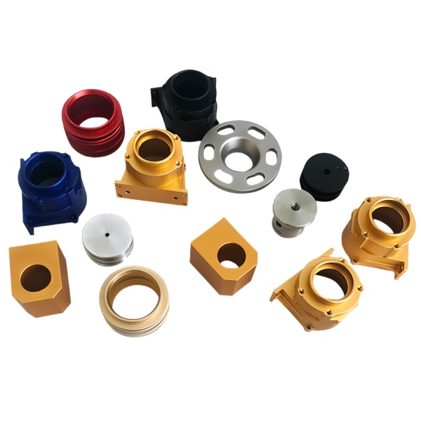
The Assorted Anodized Aluminum and Brass Machined Fittings arrive at our shop as mixed-material kits: one part number in the family calls for 6061-T6 aluminium under a Type II anodize, the next for C36000 brass in the raw turned state, and a third pairs both metals in one assembly. Turning them to size is the straightforward half of the work. The engineering that decides whether the kit actually assembles happens around the anodic build-up on finished diameters, the thread class called out on the tapered features, and the routing split between two metals that share nothing on a speeds-and-feeds sheet. This page walks through those decisions the way we handle them on the floor.
Anodizing changes the diameter you already turned to size
Anodic film grows in two directions at once: roughly half of it forms into the substrate and half builds outward, so the net dimensional change on any surface is about half the film thickness. A Type II sulfuric film specified between 8 and 12 µm therefore adds 4 to 6 µm per surface — 0.004 to 0.006 mm on a diameter. Against the +/-0.03 mm band we hold on machined features, a single anodize pass quietly consumes a fifth of the tolerance before the part has done anything at all. Type III hardcoat is worse: 25 to 50 µm of film means 0.012 to 0.025 mm of growth per surface, which is enough to turn a clearance bore into an interference fit by itself.
We handle this in the process plan, never at final inspection. Male diameters that carry the coating are turned undersize by the predicted growth; female features are bored oversize by the same amount. Where the drawing allows, we mask threads and sealing seats instead — wax masking on the flanks, silicone plugs in tapped holes — because a 60-degree thread form coated on both flanks shifts the effective pitch diameter in a way a ring gauge will find on the first turn. Hardcoat on a close-fitting cylindrical feature is either masked or ground back after coating; those are the only two honest answers, and the quotation states which one applies rather than leaving it to chance on the plating floor.
Two metals on one kit means two cutting documents, not one compromise
C36000 free-machining brass carries roughly 3 percent lead that behaves as an internal chip breaker. It turns cleanly at 90 to 130 m/min with uncoated carbide, dry or with a trace of lubricant, and the swarf comes off in short curls instead of strings. 6061-T6 wants the opposite setup: 250 to 400 m/min, polished or PCD edges, flood coolant, and positive-rake geometry sharp enough to shave rather than push, because aluminium builds up on a dull edge and drags the diameter wherever it pleases. A single shared program with averaged parameters ruins both parts — too slow and too soft-edged for the aluminium, and the wrong edge preparation leaves the brass surface smeared rather than cut.
So the routing splits by part number, not by press availability. Each material runs its own program, its own tool-offset sheet and its own first-article sign-off before volume is released. Swarf is segregated at the machine, because brass and aluminium chips are both worth recovering only while they are unmixed. When the kit ships, the process record tracks which part numbers ran on which route, so if a dimensional drift shows up downstream we can trace it back through the actual parameter set that cut the batch rather than through a guess.
Tapered and parallel threads on fittings seal differently — and are cut differently
These fittings mix NPT tapered threads with BSP parallel threads, and the distinction is functional, not cosmetic. NPT seals on the flanks of a 1:16 taper — 1 degree 47 minutes included — with a 60-degree thread form; wrench-tight engagement lands roughly three to four turns past hand-tight, and the seal is made where the flanks interference grows along the taper. BSP parallel parts have a 55-degree form that does not seal on its own at all: the joint depends on a bonded seal, a shoulder, or a compressible seat on the end face. Cutting both well means separate inserts — 60-degree profile tooling for NPT, 55-degree for BSPP — and separate gauge regimes, because an NPT ring gauge tells you nothing useful about a parallel thread.
Threads that will be anodized get one more decision. The coating on the flanks of a parallel thread effectively grows the pitch diameter by twice the flank build-up, which can push a 6g thread past its class limit after plating. We either mask the thread entirely or cut it deliberately toward the lower sixth of the tolerance so the finished, coated thread lands inside the band. Which route we take is written into the traveller; it is not a decision the anodizing line makes on our behalf.
Edge condition is the last piece of the thread story. A fitting’s entry chamfer has to survive coating without chipping the film, so we cut chamfers at 0.5 to 1 mm × 45 degrees rather than leaving a sharp lead-in, and we deburr the crest root before anodize rather than after — a burr under a ceramic film becomes a bonded defect that no post-coating touch-up can remove. On brass fittings destined for flare or compression service, the sealing cone is turned in the same setup as the thread, because concentricity between the cone and the pitch diameter is what keeps the joint from weeping at pressure, and splitting them across setups squanders that alignment for no cost saving.
Choosing between 6061-T6 and brass when the drawing leaves the alloy open
Customers sometimes send a fitting family with the alloy left as an option, and the trade-offs are worth naming plainly. 6061-T6 carries a yield strength around 276 MPa and anodizes into its own corrosion protection — the oxide is the finish and the shield in one operation. C36000 yields far lower in the annealed state but machines so freely that complex external profiles cost meaningfully less per feature, and its conductivity and bearing behavior against steel make it the default for fuel and pneumatic service. Put both metals in direct contact in a salt-bearing environment, though, and the aluminium becomes the sacrificial side of a galvanic pair; in those assemblies we either isolate the joint through the anodize thickness or redesign the contact.
For potable-water fittings we flag the lead content of standard C36000 at the quotation stage rather than at delivery, and offer the lead-free Eco Brass grades as the substitute. They machine harder — speeds drop, tool life shortens, the price per feature rises — but the substitution is a known quantity on our floor and we quote it with real numbers.
How we verify anodized and brass fittings before they ship
Every batch of this fitting family is released against a documented check sequence, run per lot rather than per promise:
- Thread verification with calibrated ring and plug gauges — NPT tapered features gauged for engagement turns, BSP parallel features gauged for class — performed after any coating or plating operation, on the finished part as it ships.
- Coating thickness by eddy-current probe per ASTM B244 on five points per sampled part, read against the drawing’s film specification, with masked features spot-checked for coating creep onto the masked zone.
- Salt-spray exposure per ASTM B117 to the hours the drawing calls out, run on witness coupons processed with the batch in the same tank load.
- Sealing integrity on sampled NPT fittings, pressurized to 1.5 times the service pressure with the joint assembled at the specified wrench engagement, held for leak observation rather than assumed from flank theory.
- Dimensional report against the signed first article, covering the diameters that carry the anodic growth compensation, so the undersize turning decision is confirmed closed-loop on every lot.
- Material certification per heat for both the aluminium and the brass stock, filed against the part numbers that consumed it.
The point of the sequence is that each of the four engineering decisions above — coating growth, routing split, thread class, alloy choice — has a check that catches it if the process drifted. A fitting that passes all six has been verified against the way it was actually made, not against the way it was supposed to be made.
You will find this part in our CNC Machining Parts range. Process notes, common materials and inspection points for every product in the family are collected across the cnc machining parts pages.
Specifications
| Item | Assorted Anodized Aluminum and Brass Machined Fittings |
|---|---|
| Brand | AUNOV |
| Designing | Send drawings, or send a sample to be measured, the quotation comes back with a manufacturability review attached. |
| Tooling | Our own toolroom designs and builds every die, held under your part number. |
| Samples | Samples for approval come with a full dimensional report and mill certificate. |
| Materials | Aluminium leads the stock list for this part, alongside carbon steel (SPCC / DC01), 304 / 316 stainless steel, brass and copper, per the drawing. |
| Surface finish | Surface treatment per the drawing: plating, e-coat, powder coating, anodising, passivation, fixed at the drawing review. |
| Processing | Multi-stage drawing, annealed in line where wall thinning calls for it, then pierced and CNC-machined in house. |
| Equipment | Mechanical presses 5-250 T and hydraulic presses 250-500 T, CNC turning centres, plus a climate-controlled CMM room. |
| Tolerance | Drawn tolerances held to +/-0.1 mm, with machined features to +/-0.03 mm. |
| Delivery terms | FOB as standard, DDP available for EU and US destinations, T/T and L/C; D/P on repeat accounts, call-off scheduling supported. |
Related Products



Request a Quote for This Part
Send a drawing or sketch — get material advice, tooling cost and a per-piece price within 24 hours (working days).