
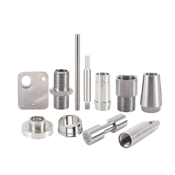
Pins, bushings and blocks are three different jobs
They arrive on the same drawing package, they are machined on the same equipment, and they are usually described together as “small machined steel parts”. But a pin, a bushing and a mounting block are three separate engineering functions, and a specification written for one of them will be wrong for the other two. The pin’s job is to locate or to transmit shear. The bushing’s job is to provide a wear surface and a defined clearance. The block’s job is to hold something rigidly in position. Different jobs, different controlling dimensions, different failure modes.
AUNOV machines steel pins, bushings and mounting blocks on CNC turning centres and mills to ±0.03 mm on machined features, with plating, coating or passivation per the drawing. This page separates the three so that a mixed order gets an inspection plan that reflects what each part is for.
| Part | Primary function | Controlling dimension | Typical failure mode |
|---|---|---|---|
| Pin | Locate two parts, or carry shear across a joint | Diameter fit and straightness; shear area if loaded | Bending, shear, or fretting wear at the fit |
| Bushing | Provide a replaceable wear surface and a defined running clearance | Bore, wall thickness, roundness, and the interference of its own outer fit | Bore wear, ovality, or loosening in its housing |
| Mounting block | Hold a component in a rigid, located position | Feature positions relative to a common datum; flatness of the mounting face | Loss of position accuracy, or distortion when bolted |
The pin: shear, fit and the two diameters that matter
A pin has two jobs that are often conflated. As a locator, it must position its two parts accurately, which is a fit question. As a shear element, it must carry a transverse load without bending or shearing, which is a strength question. A pin can be excellent at one and inadequate at the other, and the drawing frequently specifies only the fit.
- Locating pins are specified by fit, and the fit is a joint property. The hole in the mating parts and the pin diameter together define the clearance. If the pin is to a ground tolerance and the holes are drilled to a general tolerance, the realised fit is dominated by the holes, which means the pin’s accuracy is largely wasted. Conversely, a pin pressed into an undersized hole will deform the surrounding material and distort the part it is locating. The correct specification names the fit grade and identifies which component owns the tolerance.
- Shear pins are specified by material and section. The shear area is the pin’s cross-section at the shear plane, and if the pin is in double shear there are two planes and twice the area. What matters practically is that the pin’s grade is stated, because a low-carbon pin and a hardened alloy pin of the same diameter have very different shear capacities, and the difference is what decides whether the pin shears before the joint it protects is damaged.
- Straightness is the attribute that is most often omitted and most often needed. A pin that is straight to within a few micrometres over its length will assemble by hand. A pin with a bow of 0.05 mm over 50 mm may require a press to install and may not seat fully, which is then interpreted as a hole problem. Straightness over the functional length should be specified for any pin longer than about five diameters.
- End condition is a design feature. A chamfer assists assembly and reduces the chance of shearing a burr into the bore. A radiused end is preferable for a pin that will be struck. A threaded end or a cross-hole for a retaining feature changes the pin’s section at that point and should be positioned away from the shear plane.
The bushing: three surfaces and three different requirements
A machined bushing is deceptively simple. It has an outer surface that fits the housing, an inner surface that forms the running clearance, and two end faces that position it axially. Each has a different requirement, and specifying them with one tolerance is the classic mistake.
- Outer diameter: the fit to the housing. If the bushing is pressed in, the interference must be enough to prevent it moving under load and not so much that it yields the housing or distorts the bore. On steel bushings in steel or aluminium housings, the interference is typically expressed as a diametric range and the resulting bore contraction must be predicted, because pressing the bushing in will reduce the bore by roughly the interference multiplied by the ratio of the wall stiffnesses. Bushing bores are therefore commonly machined slightly oversize before pressing, or finished after pressing, depending on the accuracy required.
- Inner bore: the running clearance and its roundness. The clearance is a design number set by the required film thickness or the maximum acceptable play, and the bore’s roundness determines whether that clearance is uniform around the circumference. A bore that is correct on diameter and oval by 0.01 mm has half the intended clearance at two points. Where a shaft rotates in the bushing, this produces uneven wear and, in a plain bearing, an impaired hydrodynamic film.
- End faces: axial location and squareness. A bushing with a flange locates by its flange face, which must be square to the bore, or the bushing will cock in its housing and the bore will be misaligned. A flangeless bushing locates by one end face, and that face’s squareness matters for the same reason. Squareness is a separate tolerance from flatness and needs to be stated separately.
Two more attributes belong on a bushing drawing almost every time. The first is a lubrication feature, if one is required: a groove, a cross-hole, a spiral, or a pocket. Where the feature is, and whether it is on the loaded side or the unloaded side, is a functional decision that affects the bushing’s life. The second is the bore’s surface finish, which determines both wear rate and, where a seal runs against it, whether the seal will survive. A bore with a continuous helical tool mark will pump lubricant or fluid along its length.
The mounting block: position retention, not strength
A mounting block is usually a straightforward rectangular body with bores, slots and a flat mounting face, and it is tempting to treat it as a piece of structure. Its real job, though, is to hold features in a fixed relationship, so its controlling attribute is geometric rather than structural.
- Feature position relative to a stated datum. The block’s mounting holes define where it sits; every other feature is measured from those. If the drawing dimensioned features from multiple datums or chained the dimensions through intermediate features, the tolerance accumulates and the block may accept the mounting bolts while placing the held component incorrectly. The right specification uses one primary datum and controls the rest to it, typically by position tolerance rather than by chained dimensions.
- Flatness of the mounting face. A block bolted down on a face that is not flat will be pulled into the shape of whatever it is bolted to, which distorts the bores and defeats the positional accuracy. Flatness on the mounting face is therefore a functional requirement, and it should be measured on a surface plate rather than inferred. Where the block is bolted to a machined surface, matching flatness values on the two faces is the appropriate specification.
- Distortion under bolt load. A thin block with bolts near its edges will bow when tightened, and bolting it down is not a neutral operation. If the block’s features are referenced to its own mounting face while it is free on the table, but the block is subsequently distorted by bolts, the reference is invalid. For critical blocks we specify the mounting face flatness in the bolted condition, or we check the block on a fixture that simulates the bolted condition.
- Wall thickness around bores. A bore close to an edge leaves a thin ligament that deforms under load and can crack. Keep a minimum wall of at least one bore diameter around a loaded bore, and more where the load is cyclic.
Steel grade choice across the three parts
The steel grade is often inherited from the previous design, which means the properties actually required were never identified. The three part types pull toward different grades.
| Requirement | Grade direction | Reason |
|---|---|---|
| Maximum shear capacity in a small pin | Medium-carbon or alloy, through-hardened | Shear strength scales with hardness; a hardened pin resists shear in a section that a mild steel one cannot |
| Maximum toughness in a pin that must yield safely | Low-carbon, case-hardened or left tough | A pin intended as a sacrificial element should bend rather than shatter |
| Wear resistance in a bushing bore | Through-hardened, or case-hardened, or a bronze alternative | The bore is the wear surface; hardness determines life, but a hardened bore in a soft shaft just moves the wear |
| Machinability and stability in a block | Free-cutting or low-carbon, stress-relieved | Blocks are close-tolerance and dimensionally large, so dimensional stability during and after machining matters more than strength |
| Corrosion resistance anywhere | Plating, or a stainless steel grade | Carbon steel needs a barrier; stainless steel removes the barrier question and changes machinability and galling behaviour |
Notice the interaction between a pin and the bore it runs in. Hardness is only useful in the context of the pair. A hardened pin in a soft bore will wear the bore; a soft pin in a hardened bore will wear the pin, which is often the preferred outcome because the pin is the cheaper part to replace. Deciding which part is intended to wear first is a real design decision, and it should be recorded.
Plating, and the dimensions it consumes
Most steel parts in this family are plated, usually with zinc or zinc-nickel for corrosion protection, and sometimes with a harder coating for wear. Plating adds a layer, and on a precision part the layer is a significant fraction of the tolerance.
- A zinc layer of 8 micrometres per surface adds 0.016 mm to a diameter. On a pin with a 0.02 mm total tolerance band, that is 80 percent of the tolerance. The pin must therefore be cut undersize by the anticipated plating, or the plating must be masked from the fit, or the fit must be specified after plating and achieved by grinding after the coating.
- Threads are the most sensitive feature. A plated thread needs a pre-plate pitch diameter allowance, and the amount depends on the plating build on the flanks, which may differ from the build on a plain surface.
- Hydrogen embrittlement is a real risk for hardened steel. High-strength steel parts that are acid-cleaned and electroplated can absorb hydrogen, and the resulting embrittlement causes delayed brittle fracture, sometimes days after plating. Any hardened pin or bushing in this family that is electroplated should carry a post-plating baking requirement in the specification. This is not a precaution for the faint-hearted: it is a standard requirement for parts above roughly 1000 MPa tensile strength.
- Plating changes fits, and fits define function. Because a pin’s function is mostly its fit, a plating specification that ignores the dimensional effect is a functional specification, not a cosmetic one, and it should be treated with the same care as the tolerance above it.
Inspection for a mixed order
- Pins. Diameter at three positions along the length to detect taper, straightness over the functional length, fit verification with a gauge or a mating hole, end chamfer and deburring, and hardness verification if the pin is a specified shear element.
- Bushings. Outer diameter and its roundness, bore diameter and roundness, wall thickness at several points around the circumference, squareness of the locating face to the bore, and bore surface finish with a check for continuous helical marks.
- Mounting blocks. Feature positions on the CMM from a single datum, flatness of the mounting face on a surface plate, parallelism where relevant, bore diameter and roundness, and a check for distortion in the bolted condition where the specification requires it.
- All parts. Plating thickness on a representative surface, thread gauging where threads exist, and hydrogen embrittlement baking records for hardened plated parts.
Deciding which member should wear first is the real question
Should the pin be harder than the bore it goes into?
Deciding which member wears first is the real question. A hardened pin in a soft bore protects the pin and destroys the bore, which may be the more expensive member. In most cases the intended sacrificial part is the smaller, cheaper, more accessible one, and the hardness should be chosen to match that intention.
Why did a pressed bushing change the bore diameter?
Pressing in an interference-fit bushing compresses it, and the bore shrinks by an amount that depends on the interference and on the relative wall stiffnesses. If the bore is dimensionally critical, either predict the shrinkage and machine oversize, or press the bushing in and finish the bore afterwards.
Does a mounting block need heat treatment?
Only if it needs hardness or if dimensional stability requires stress relief. For most blocks, a stress-relieved low-carbon or free-cutting steel gives the machinability and stability that the part actually needs, and adding hardness adds cost without benefit.
How do I avoid hydrogen embrittlement on plated pins?
Specify the post-plating bake for hardened parts, and tell us the hardness range so that the bake requirement can be set correctly. If the pin does not need to be at high hardness, lowering the hardness and avoiding the problem entirely is often the better route.
Our CNC Machining Parts range is where this part sits. The cnc machining parts pages carry the process notes, common materials and inspection points behind every product in the family.
Specifications
| Item | Steel CNC Machined Pins Bushings and Mounting Blocks |
|---|---|
| Brand | AUNOV |
| Designing | Send us your 2D drawing, or mail a sample for measurement, a manufacturability review comes back with the quotation. |
| Tooling | Every die designed and built in our toolroom, stored under your part number. |
| Samples | Samples for approval come with a full dimensional report and material certification. |
| Materials | Carbon steel (SPCC / DC01) leads the stock list for this part, alongside 304 / 316 stainless steel, aluminium, brass and copper, per the drawing. |
| Surface finish | Plating, e-coat, powder coating, anodising or passivation as the drawing calls out, per your print. |
| Processing | Staged deep drawing, with in-line annealing where the draw ratio requires, pierced and finish-machined on the same floor. |
| Equipment | 5-250 T mechanical presses plus 250-500 T hydraulic presses, CNC cells plus a temperature-controlled CMM room. |
| Tolerance | +/-0.1 mm on as-drawn features, +/-0.03 mm after machining. |
| Delivery terms | Prices FOB, with DDP for EU and US on request, T/T and L/C accepted, D/P for established customers, scheduled call-offs welcome. |
Related Products



Request a Quote for This Part
Send a drawing or sketch — get material advice, tooling cost and a per-piece price within 24 hours (working days).