
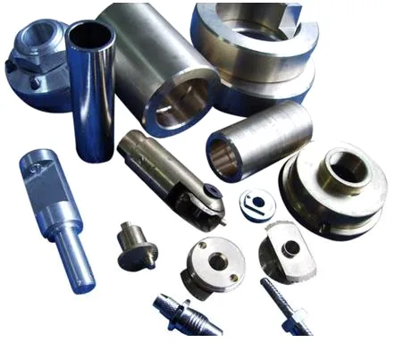
A small gear cut on a lathe looks like an extension of turning work and it is not, because the gear’s whole purpose is to have teeth, and teeth bring three problems that no other turned feature brings: the pitch diameter has to be exactly right or the gear will not mesh, the tooth profile has to be generated rather than cut directly, and the gear’s accuracy changes over its life as the teeth wear.
So this page is about what a gear needs beyond turning, and about why a gear and a fitting on the same bar-fed machine are two different products.
Pitch diameter, which is the number that matters
Two gears mesh only if their pitch diameters and their centre distance are in a defined relationship. Everything else about the gear – the outside diameter, the root diameter, the tooth count – is derived from the module and the pitch diameter, and the pitch diameter is the number that has to be held between the gear and whatever it drives.
Three practical consequences on a machined gear:
- Pitch diameter tolerance is tight and it is a specific tolerance, not a general one. A gear that is 0.02 mm oversize on its pitch diameter will run with more backlash than intended and will carry its load on one side of the tooth rather than across the flank. For a small gear in a light-duty instrument drive that may be acceptable; for anything with real torque it will show as wear.
- Runout on the pitch circle is separate from size. A gear that is within its pitch diameter tolerance but has runout will produce a periodic variation in the drive – a “chatter” at the tooth engagement frequency. On a gear driving a load this is audible and it is a fatigue load.
- The centre distance is a mating dimension. The gear’s pitch diameter plus the driven gear’s pitch diameter divided by two is the centre distance, and if the centre distance is fixed by a housing then the two gears’ pitch diameters have to share the tolerance between them. On a pair of gears in a machined housing, the pitch diameter tolerances and the housing’s bore positions have to be specified as one stack, and this is where gear sets go wrong.
How the teeth are made, and what it does to the tolerance
Teeth are generated, and the generation method is what decides the accuracy achievable and the surface quality. On a lathe the options are these, and they are genuinely different products.
Hobbing
A hob is a multi-threaded cutting tool that generates the teeth by rolling. It is the standard method and it has two significant advantages: it produces an excellent surface finish, and because it is a generating process it will cut a module and a profile that an involute cutter cannot. Hobbed gears have good flank finish and good accuracy.
Form milling with an involute cutter
A single form cutter cuts the space between teeth one at a time. This is the traditional lathe method and it is still widely used for small gears in modest volumes.
- It cannot produce a true involute profile unless the cutter is a true involute form, and the cutter’s own accuracy sets the gear’s accuracy. The root and the tip will not be exactly correct even with a good cutter, and the error appears most strongly on small gears where the cutter’s error is a large fraction of the tooth.
- Cutter wear matters directly. Every gear cut wears the cutter and the worn cutter produces gears that are out of profile. On a small gear this means the tool change interval is short and it is the dominant cost in the operation.
- The surface finish is machined, so it is good but not as good as a hobbed gear, and it will have the characteristic scallops left by the cutter.
Gear shaping, broaching and grinding
- Shaping produces the teeth by reciprocating a tool; it is a slower process but it produces a true involute and a good finish, and it suits the larger gears that a lathe cannot hold.
- Broaching is a high-volume method with an excellent finish and a very good accuracy, and the tooling cost is high. It is the right answer on volume and wrong at low volume.
- Grinding – particularly the flank grinding of a gear that has been generated roughly – is how the highest accuracy is obtained. A gear that will be used as a reference or in a high-accuracy drive will be generated and then ground, and the grinding removes the material that the generating process left.
The point worth making on a drawing is: state the accuracy class the gear has to reach, and let the process meet it. Specifying “these are involute spur gears, accuracy grade per the applicable standard, pitch diameter held to the band below” allows hobbing or shaping or grinding as appropriate. Specifying the process instead forecloses the shop’s ability to choose the cheaper route that achieves the same result.
Backlash, and where it has to come from
Backlash is the deliberate gap between the meshing teeth, and where it comes from matters more than its size.
- Backlash by tooth thinning – the gear is generated with the tooth’s thickness reduced – is the normal arrangement. It means the gear’s pitch diameter and profile are correct and the backlash is added at the tooth. This is what a gear should do.
- Backlash by centre distance increase is what happens if the gears are generated at nominal thickness and the housing’s bores are made slightly further apart. It works, but it means the gear’s accuracy is being spent on the centre distance, and any variation in the housing goes straight into the backlash and the load distribution.
- Backlash on a coarse-pitch gear will be large in absolute terms because backlash scales with pitch. A gear with a 1.5 mm pitch has several times the backlash of a 0.8 mm pitch gear at the same quality level. On a fine mechanism that matters and it should be checked rather than assumed.
- Directional backlash. On a gear with asymmetric teeth, the backlash differs between the driving and driven directions. If the drive is used in both directions, both values matter and the tooth’s modification has to be specified rather than left to the cutter’s standard.
Material, and why a gear is often the sacrificial element
Carbon steel, 304 and 316 stainless steel, aluminium and brass, with special grades sourced when volumes justify. On a gear the material question is a wear question with a specific answer.
- Steel or case-hardened steel is the normal answer for anything with load. The teeth carry the load and they wear, and a case-hardened gear has a hard tooth surface over a tough core, which is exactly what a gear needs – hardness for wear and toughness for the impact of starting and stopping.
- Brass and bronze are used for instrument and clockwork gears, and they are chosen deliberately: a brass gear running against a steel worm or a steel pinion will wear first, it is quiet, and it will not gall into the mating part. On a low-torque instrument drive, engineering the sacrificial element to be the gear is the correct decision.
- Aluminium is used for light-duty gears and for a part that must be light. It is not a good wear material against a steel mate and it has a low fatigue strength, so an aluminium gear in a loaded drive will fail at the tooth root rather than by wear.
- Stainless Steel is chosen where corrosion or cleaning dominates – a food-adjacent or a medical or a marine gear. It galls readily against a steel mate, so on a stainless steel gear the mating material and the lubrication both matter, and a stainless steel gear running dry against a steel pinion will destroy both.
The fitting on the same part, and the turning
Where the item is a fitting rather than a gear, the content is the familiar one – the thread, the bore, the hexagonal or knurled interface – but there are two gear-adjacent points worth making.
- On a gear and a fitting made as one part, the bore and the pitch diameter have to share a datum. If the gear’s teeth are cut with the bore as the reference, the bore’s accuracy is what the gear’s accuracy becomes. That is the correct arrangement and it means the bore must be finished before the teeth are cut.
- On a small turned fitting, the same one-setup discipline applies – turn-mill machining with critical diameters finished in one setup, and batch records filed so a repeat order starts from approved data. On a gear this matters more than on most parts, because a gear’s pitch diameter and a gear’s bore are a relationship, and a re-chucked relationship is a relationship that has been spent.
Finish selected from the drawing – plating, coating, anodising or passivation, with the agreed finish travelling with the part number. On a gear, finish has one rule that overrides the rest: do not coat the teeth. A plating on the tooth flank changes the profile and the pitch diameter, and a coating on a tooth will wear away in service and leave a gear with an inconsistent profile. Where a gear needs corrosion protection, the teeth should be masked, or the gear should be made from a corrosion-resistant material rather than coated.
On a gear the tight band belongs to pitch diameter, not the outside
+/-0.02 mm general machining with tighter bands on the flagged dimensions, and critical dimensions carrying CMM data with the shipment. On a gear the flagged dimensions are specific and none of them is the outside diameter.
- Pitch diameter, to a band, on every part.
- Runout on the pitch circle, reported separately from the pitch diameter’s size, because they are different characteristics and a gear can be correct in one and wrong in the other.
- Tooth thickness or backlash, as the requirement rather than as a derived number.
- Concentricity of the teeth to the bore, which is what makes the gear concentric to its shaft and therefore what keeps the load on one side of the tooth.
- Face width and its perpendicularity to the axis on a gear that must run true in a housing.
- The bore, to its own fit requirement, and the bore’s concentricity to the teeth as a separate characteristic.
- Surface finish on the tooth flanks, where the process produces it differently – and this is worth stating because a ground gear and a milled gear differ measurably in flank finish and it is a real difference in the gear’s behaviour.
Everything else – the outside diameter, the hub’s dimensions, the length – at the general band. On a gear those do almost no functional work.
Gear accuracy is a different measurement from anything on a CMM
- Gear measurement on a gear-testing machine, measuring pitch diameter, runout, profile and lead deviations, reported as an accuracy result rather than as two dimensions. This is the inspection that matters and it is a different measurement from anything on a CMM.
- Functional mesh check against the mating gear on a sample, where a mating gear is available. A gear set that measures correctly individually can mesh badly if the two were generated to different profile modifications.
- Backlash measured in assembly with the mate, or calculated and stated.
- CMM data on the bore, the hub and the flagged dimensions.
- Tooth flank surface finish where specified, and edge condition on the tooth tips.
- Batch records filed against the part number, because a gear set is normally produced and used together and a repeat order has to match the original.
The wear item, or the part that has to outlast its mate
Is this gear’s job to be the wear item, or is it supposed to outlast the part it drives? A gear driven by a worm, or by a pinion, or by anything that is harder, is naturally the sacrificial element and the design should let it wear – which means a material that wears quietly and does not gall, and possibly teeth that are deliberately slightly softer. A gear driving a compliant or a light-load member may need to outlast it, and then it wants to be hardened and it wants its profile to be ground. These two answers lead to different materials, different processes, different accuracy requirements and different inspection. There is also a third question that is worth asking and that is almost never asked: what is the expected life, and is the gear replaceable when it has worn? A gear that is machined rather than moulded and that is accessible can be a consumable, and once it is treated as one the design can be considerably simpler – it does not need to last the life of the assembly, so it can use a cheaper material and a less demanding accuracy. That conversation is much cheaper at enquiry stage than it is after the gearbox is assembled.
You will find this part in our CNC Machining Parts range. Process notes, common materials and inspection points for every product in the family are collected across the cnc machining parts pages.
Specifications
| Item | Stainless Steel CNC Turned Fittings and Gears |
|---|---|
| Brand | AUNOV |
| Designing | Your drawing sets the part – DFM notes are returned before any tooling is cut; the approved drawing is kept as the controlled master. |
| Tooling | Dies are made and maintained in house, which keeps tooling lead time and cost under control. |
| Samples | First-article samples ship with a dimensional report and material certificate, so the approved first article becomes the gauge reference, and the signed sample is kept for future reorders. |
| Materials | Carbon steel (SPCC / DC01), 304 / 316 stainless steel, aluminium and brass are held on site; special grades are sourced to the drawing when volumes justify. |
| Surface finish | Finish selected from the drawing: plating, coating, anodising or passivation; the agreed finish travels with the part number. |
| Processing | Turn-mill machining, critical diameters finished in one setup; batch records are filed so a repeat order starts from approved data. |
| Equipment | Bar-fed CNC turning centres plus 3- and 4-axis machining centres, with CNC turning centres for secondary operations and CMM inspection. |
| Tolerance | +/-0.02 mm general machining, tighter on flagged dimensions; critical dimensions carry CMM data with the shipment. |
| Delivery terms | FOB, CIF or DDP per Incoterms 2020, T/T with deposit and L/C for larger runs; price breaks tie to annual volume. |
Related Products



Request a Quote for This Part
Send a drawing or sketch — get material advice, tooling cost and a per-piece price within 24 hours (working days).