
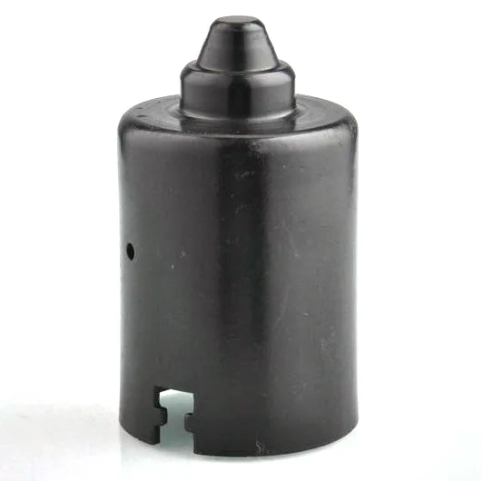
The mechanics of drawing a wiper housing wall
Strip the labels away and a sheet metal forming wiper motor housing is a controlled fight between three forces: the punch pushing metal into the die, the blank holder clamping the flange so it does not fold, and the sheet itself resisting thinning beyond what the design can tolerate. Everything we do at the press is arbitrage between those three. Get the balance right and a 70 mm shell comes off the press in under a second, wall thickness within 5% of nominal, ready for the rest of the motor. Get it wrong and you see wrinkles at the wall, cracks at the radius, or an oval shell that no bearing will sit in straight.
Draw ratio: the first number we calculate
For a cylindrical wiper housing the governing ratio is blank diameter over punch diameter. Most wiper housings in 0.8-1.5 mm sheet land between 1.6 and 1.9 – safely inside one-stroke territory for DC01, which tolerates a limiting draw ratio near 1.9-2.0. When a customer’s design pushes past 2.0, the honest conversation is not “try harder” but “redesign”: increase the corner radius, thicken the sheet, or split the draw into two operations with an anneal-free intermediate. We run the calculation before quoting because a draw ratio that barely works in the lab will barely work in production too, and production is where the costs live.
Where the metal thins – and how much is allowed
In a drawn shell the critical section sits just above the punch radius, where tension from drawing the wall combines with bending over the radius. A healthy wiper housing shows 3-8% thinning there. Past roughly 12-15%, the wall becomes the weak link: it thins further with every stroke variation and eventually necks. Our acceptance rule for motor housings is wall thickness within -8% of nominal at the critical zone, verified by ultrasonic spot checks on first articles and by periodic sectioning on a defined audit cadence. The figure matters because the flange of the bushing bore seats against that wall – a thin wall there means a pressing operation that cracks housings downstream.
Wrinkles, draw beads and the blank holder window
Wrinkling happens when circumferential compression in the flange exceeds the stiffness the blank holder provides. The fix is either more clamp pressure – until the sheet starts tearing instead – or a draw bead that adds controlled restraint around the perimeter. The working window between wrinkling and tearing is real but finite, and it narrows with lubricant batch, coil batch and press speed. This is why we do not quote a draw without specifying the lubricant: a chlorinated-free drawing oil at a defined viscosity is part of the process, not a consumable afterthought. When a customer’s shell shows intermittent wrinkles on their existing supplier’s parts, the cause is almost always at the edge of that window, and the fix is a bead profile change, not “better operator attention”.
Springback and ovality in shallow versus deep shells
Counterintuitively, shallow wiper covers spring back more than deep ones – less plastic deformation means more elastic recovery, and the flange lifts or the walls flare. Deep shells hold shape better but risk tearing. Ovality, meanwhile, comes from anisotropy in the coil: rolled sheet flows more easily along the rolling direction, so a circular shell tends toward slightly oval with the long axis along the coil. The countermeasure is specifying sheet with a tight plastic-strain-ratio band, or accepting a few tenths of ovality and letting the restrike station square it. We do the latter for most wiper programmes: the restrike costs a station in the die but removes an entire class of downstream fit problems.
Forming limits we check before promising anything
- Corner radii. Punch radius below about 4t invites thinning cracks; below 2t, cracks are near-certain in steel. If the drawing asks for tighter, we quote a machined or coined alternative for that feature.
- Ears and local forms. Mounting ears formed from flange material pull extra metal and can starve the adjacent wall. We blank-develop the ear shape so it feeds rather than fights the draw.
- Cable-exit slots. Slots pierced before drawing tear at the draw radius; after drawing, they distort the wall. The workable window is pierced between operations with the shell still strip-supported – a die-design question, not a press-setting question.
The drawing needs four things, not two
Send the drawing with sheet thickness, material grade, and the two tolerances that actually matter: bushing-bore concentricity and flange flatness. Add annual volume. We will return a draw-ratio sanity check, the number of die stations, and a sample timeline – typically first articles three to four weeks after die approval, because the forming physics of a wiper housing are well mapped and the die either works in week one or gets one corrective loop.
Is wall thinning at the top edge acceptable?
Our current housings show wall thinning at the top edge – is that acceptable?
Depends where the bushing seats. Thinning at the open edge away from any functional face is cosmetic; the same percentage at the critical section just above the punch radius is a latent crack. Send us a sectioned sample and we will mark it up against our audit rules.
Can you hold the bore concentric to the OD within 0.05 mm?
Yes, but only with the bore pierced in-strip while the shell is supported – a loose-part piercing operation cannot hold that figure reliably at volume. It is a die architecture decision, and it is one of the main reasons progressive dies dominate this part family.
Does forming direction matter for our assembly?
Only through ovality, and the restrike handles that. If your assembly press-fit is marginal, tell us – we will tighten the restrike calibration rather than let you shim at the line.
This part belongs to our Automotive Motor Components range. The automotive motor components pages collect the process notes, common materials and inspection points behind every product in the family.
Specifications
| Item | Sheet metal forming wiper motor housing |
|---|---|
| Brand | AUNOV |
| Designing | Your drawing sets the part – DFM notes are returned before any tooling is cut; changes are priced before they are made. |
| Tooling | Progressive and drawing dies are designed and built in house, so tooling lead time stays under our control, and first-article timing is measured from the tooling start date. |
| Samples | Pre-production samples come with a full inspection report, so the approved first article becomes the gauge reference, and the signed sample is kept for future reorders. |
| Materials | Carbon steel (SPCC / DC01), 304 / 316 stainless steel, aluminium, brass and copper – the grade is matched to the duty of this housing. |
| Surface finish | Adhesion comes from phosphating, followed by powder coating, e-coating or zinc plating; visible faces get chrome or nickel. |
| Processing | From coil or blank, deep drawing with in-process annealing thins walls evenly; the sequence then runs trim, pierce, form and finish. |
| Equipment | Mechanical capacity 5-250 T and hydraulic 250-500 T, with annealing ovens and CNC turning and machining centres alongside. |
| Tolerance | +/-0.15 mm typical on formed parts, +/-0.3 mm on large covers; the die decides the achievable band. |
| Delivery terms | FOB, CIF or DDP per Incoterms 2020, payment by T/T or L/C, quoted in USD or EUR; each volume tier carries its own quoted price. |
Related Products

Request a Quote for This Part
Send a drawing or sketch — get material advice, tooling cost and a per-piece price within 24 hours (working days).