
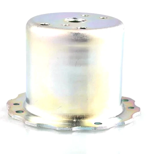
The housing as a thermal and mechanical structure
There is a second way to look at a stepping motor housing, and it is the one an equipment builder cares about. A stepper holds position by holding current, so it dissipates power continuously and runs hot even when it is not moving; it drives loads with a rotor that has inertia; and it is often mounted on a machine that vibrates and produces swarf. Seen this way the housing is not just the thing that establishes the air gap – it is the heat sink, the structural member and the barrier that keeps the inside of the motor clean. This page treats the housing as that structure, for the frames we draw for automation, machine tools, printers and instruments.
Dissipating heat without a big frame
A stepper’s winding is energised at standstill, so the motor’s continuous rating is often set by how fast its heat leaves, not by how much it can produce in a burst. The housing is the first link in the heat path – from the winding, through the stator stack, into the housing, and out to the air and to the mounting plate. Design choices follow:
- Wall and stack contact. The tighter and fuller the contact between the stator stack and the housing bore, the better the heat crosses into the shell; an air film in the fit is an insulator.
- Surface area. A drawn steel shell with a clean cylindrical outside radiates and convects more than the same mass inside a bulky casting with a rough surface, and a smooth round body is easy to keep clean.
- The mounting plate is a heat sink. A housing with a flat, perpendicular mounting face transfers heat into the machine frame; a face that only touches on one edge transfers much less. Holding the mounting face flat pays off twice – alignment and cooling.
Where a customer knows the motor will run hot, we discuss the material and the finish, because a dark, non-reflective finish radiates better than a bright plated one – a small point that matters on a frame with no fan.
Resonance: the housing shapes the noise
Steppers have well-known resonances – the mid-band resonance that can make a motor stall or howl at certain step rates, and the structural resonances of the frame itself. The housing contributes to the second: a thin, long shell has its own natural frequencies, and if a step rate or a mounting excites one, the motor sings. Three practical responses:
- Stiffness. A stiffer shell – thicker wall, shorter unsupported length, or a formed rib – pushes its natural frequencies up and away from the step bands.
- Damping. A firm, wide mounting contact damps vibration into the machine frame; a loose or small-contact mount rings.
- Consistency. A round, uniform shell behaves predictably; an oval or seamed shell has local soft spots that respond unevenly.
We keep the shell round and uniform and work with the customer on wall and features where a resonance is a known issue, rather than treating the housing as acoustically neutral.
Loads: rotor inertia and the machine around it
A stepper reverses direction and starts and stops under load, so the housing carries the reaction torque of every move and the radial and axial loads the driven part imposes on the shaft. Because the bearings sit in the housing, those loads land on the bearing seats and on the mounting flange. Two checks matter at design stage: the bearing seats must be stiff enough that the shaft cannot tilt under load, and the mounting flange must be strong enough that a belt tension or a gear load does not distort the face. We size the flange thickness and the seat support from the loads the customer gives us, and where the load is high we consider a heavier wall or a machined seat rather than assuming the draw alone is enough.
Keeping swarf, dust and coolant out
Steppers are used on machine tools that spray coolant, on printers that shed powder, and in automation cells that carry fine swarf. Anything that reaches the rotor gap or the bearings causes trouble, so the housing’s openings matter:
| Cable exit | The largest opening; it needs a gland, a grommet or a sealed connector so the cable hole is not a dust path. |
|---|---|
| Shaft opening | At the driven end, a lip seal or a close-fitting shield keeps coolant and swarf out of the front bearing. |
| Seams and closures | Any rolled or welded closure has to be tight; a housing that is not sealed will collect dust at the closure and let it migrate inward. |
We form a proper seat for a gland or a grommet at the cable exit and a controlled bore for a shaft seal, because an opening that relies on a loose cable to block dust will not stay sealed in service.
Drawn shell or casting: the volume question
Many stepper housings are made as drawn shells and many are cast, and the choice is largely about volume and shape:
- Drawn shell – low tooling cost for a round or square section, good for small to medium volumes and for custom frames where a casting pattern would be too expensive. Wall is uniform, the surface is smooth, and the drawn bore is a good stator seat.
- Casting – better for complex internal features, for very large frames and for high volumes where the pattern cost is amortised, but heavier for the same stiffness and slower to change.
For custom and low-to-medium volume frames – common in automation and in OEM equipment – a drawn housing usually wins on tooling cost and lead time, and it can be re-dimensioned for a new frame without cutting a new pattern. That flexibility is why we draw these housings: a new frame size is a new set of dies, not a new foundry project.
Variants and custom frames
Equipment builders rarely want the one catalogue size. They want a shaft length, a cable exit position, a bolt pattern and a mounting face that suit their machine, often in modest volumes. A drawn housing suits that pattern of demand because the tooling is modular – a change to the cable exit or the flange is a change to one station, not a redesign of the whole motor. We build these variants against a controlled drawing and keep the station change documented, so a repeat order or a variant of an existing frame starts from approved data.
A stepper housing’s envelope matches common NEMA frame sizes
- Body: 28-86 mm square or round.
- Length: 25-120 mm.
- Wall: 0.8-2.0 mm.
- Features: stator bore, bearing seats, mounting flange and bolt pattern, cable exit with gland seat, shaft seal bore, rib or stiffening feature where needed.
Whether a drawn shell runs cooler than a casting
Will a drawn housing run cooler than a casting?
A smooth round drawn shell radiates and convects well for its mass, and a flat mounting face lets heat into the machine frame; the material and finish also matter, so we discuss all three with the customer.
Can you add a rib to move a resonance?
Yes – a formed feature raises the shell’s stiffness and shifts its natural frequency, and we work from the step rates and mounting you give us.
How do you seal the cable exit?
We form a seat for a gland or grommet so the opening is positively sealed rather than relying on the cable to block dust.
Is a drawn housing economical at low volume?
Usually yes – the tooling is modular and inexpensive compared with a pattern, so custom frames and variants are practical without a large up-front spend.
Heat load, step rates and shaft loads decide the housing’s wall
Tell us the frame size and wall you want, the heat load and duty, the step rates and mounting so we can consider resonance, the loads on the shaft, the sealing you need against dust or coolant, the cable exit and connector type, and the volumes. Those inputs decide the wall, the features, the sealing and the tooling route – which is what gives a stepper a housing that stays cool, stays quiet and keeps its internals clean for the life of the machine.
This part belongs to our Automotive Motor Components range. The automotive motor components pages collect the process notes, common materials and inspection points behind every product in the family.
Specifications
| Item | Sheet metal deep drawing stepper motor housing |
|---|---|
| Brand | AUNOV |
| Designing | Quotation follows the print, not a catalogue – samples are reverse-measured into a controlled drawing; changes are priced before they are made. |
| Tooling | Progressive and drawing dies are designed and built in house, so the die charge appears as its own quotation line, and maintenance is tracked against the part number. |
| Samples | Sample parts are measured and reported before submission, so the part is proven before it is made in volume, and the signed sample is kept for future reorders. |
| Materials | Stock list: carbon steel, 304 / 316 stainless steel, aluminium, brass; the final grade is fixed at the drawing review. |
| Surface finish | Phosphating for coating adhesion, then powder coating, e-coating or zinc plating; chrome and nickel for visible faces. |
| Processing | Coil blanking, progressive drawing through 3-5 stages with anneals between, trim and pierce, then deburr and finish. |
| Equipment | The press floor pairs 5-250 T mechanical with 250-500 T hydraulic presses; an in-line annealing furnace sits on line and CNC turning covers secondary work. |
| Tolerance | +/-0.1 mm on formed features and +/-0.2 mm on overall lengths; tighter bands confirmed against the die before quoting. |
| Delivery terms | FOB, with DDP offered for EU and US addresses, payment by T/T or L/C, quoted in USD or EUR; each volume tier carries its own quoted price. |
Related Products



Request a Quote for This Part
Send a drawing or sketch — get material advice, tooling cost and a per-piece price within 24 hours (working days).