
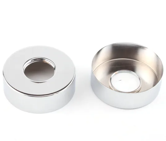
A hydroformed housing differs from a hydroformed cover in one way that changes everything: it has to do something after it is formed. A cover is finished when its shape is finished. A housing has to accept another part, carry a load, seal against something, or mount to something — and the formed shape is only the starting condition for that.
The consequence is that on a housing the tolerance story is dominated by features that hydroforming cannot produce directly. The shell is the easy part. The interfaces are the design.
Why a housing needs a machined or formed interface band
Hydroforming controls the shape of the shell and controls the wall thickness map. It does not, on its own, produce:
- A face flat enough to seal against
- A hole positional to a tight tolerance
- A thread
- A boss with a controlled axis
- A datum surface
All of these have to come somewhere else, and where they come from changes the whole process plan. There are three arrangements in common use.
- Machined after forming. The housing is hydroformed, then machined on a fixture that locates on the formed shell. Simple in principle and it inherits the shell’s dimensional variation into every machined feature.
- Separate interface features inserted before forming. A boss, a pad or a frame is welded or brazed to the preform before hydroforming, and the die shapes around it. The features are then well located because the die located them, not the shell.
- Hybrid, with a machined flat. The shell is formed to shape and a flat interface is machined on one face only, with the rest of the shell left as formed. This is the usual compromise and it is the cheapest way to get a sealable surface.
On a drawing, which arrangement is in use must be clear, because it determines whether the interface positions are forming-stage dimensions or machining-stage dimensions. That difference is a factor of five or more in achievable tolerance.
The fixture problem: locating on a formed shell
Machining a hydroformed housing requires holding it accurately, and a formed thin shell is a poor fixturing subject for three reasons.
- It distorts under clamping. A thin shell clamped at points will distort between them, and the distortion is elastic, so the part moves back when released and the machined dimension is wrong relative to the unloaded shape.
- Its own shape is the datum. If the datum is a formed face with a forming tolerance, that tolerance appears in every machined dimension.
- The wall is not uniform. The hydroform thickness map means the part has variable stiffness, so a fixture that works on the thick region may not work on the thin one.
The mitigations, in order of effectiveness:
- A purpose-made nest that supports the whole surface rather than clamping at points. Vacuum or a low-pressure conformal fixture works well on a shell.
- A datum defined on the shell in the region of lowest variation — usually where the die supported the part best, since that is where the wall is thinnest and most predictable.
- Machining in two operations with a stress or shape-stabilising step between them, so the part is not machined in a stressed state.
- Making the fixture from the part’s own data, so that the fixture matches the actual shape rather than the nominal one. On a hydroform this is often necessary because the as-formed shape is not predictable enough for a general fixture.
None of this is cheap, and the tooling estimate for a hydroformed housing should include the fixture. A fixture quoted as an afterthought is the most common cause of a machined housing arriving out of tolerance on the first batch.
Sealing: the interface the housing must not lose
Where the housing seals — to a cover, to a filter, to a pipe, to a flange — the sealing surface is the place where forming tolerance and machining tolerance meet, and it is worth being precise about which surface is which.
- A sealing surface that is machined flat and finished is the reliable answer. The cost is that all of the sealing geometry has to be machined.
- A formed sealing surface can work if the seal is compliant enough to accommodate the variation — an O-ring in a groove tolerates more variation than a flat face against another flat face. The groove itself, however, is a machined feature.
- A sealing surface that relies on the formed shell is only viable where the seal is soft and the load is low, and where the forming variation is genuinely small in that region.
The failure mode is a leak that appears only after thermal cycling, when the shell has relaxed differently from the machined face. Where a housing carries fluid, the drawing should identify the sealing surfaces explicitly and state whether they are formed or machined — and that statement should be consistent with the tolerance assigned to them.
Material and the housing’s other job
A housing is frequently also a heat exchanger or an EMI shield, and this changes the material decision in ways that are not obvious from the geometry.
- If it dissipates heat, aluminium is nearly mandatory. Conductivity is an order of magnitude better than stainless steel, and a housing that cannot conduct heat away from what it contains will overheat it.
- If it is an EMI shield, the seam is the whole problem. A hydroformed shell has a split line, and a split line is an antenna slot. Conductive gasketing along the seam is required, and the gasket groove is a machined feature.
- If it is a structural housing with a conductive requirement, a hybrid is common — an aluminium shell with a stainless steel or plated steel insert carrying wear or contact surfaces.
On an aluminium housing, the corrosion behaviour depends on the alloy. The 5000 series has good corrosion resistance and is the usual structural choice. The 6000 series heat-treats well but is less forgiving in forming and will crack in a tight radius. And a dissimilar-metal insert creates a galvanic pair that needs attention at the interface.
Wall thickness where the housing carries load or pressure
On a cover, wall variation is a stiffness variation and usually tolerable. On a housing that contains something under pressure, the thinnest point is the design limit, and the hydroform’s natural corner thinning sits exactly where a housing’s corners often carry the highest internal load.
So the specification has to be located, not general:
- A minimum wall applicable everywhere, which the corners will govern.
- Specific minimums at any boss, pad or interface location.
- A wall thickness range in any region where stiffness uniformity matters, because a housing that varies in stiffness from end to end will rattle or will amplify a vibration.
- Where a threaded feature is formed into the wall, a local minimum wall around it.
A general tolerance on the housing does not express any of this. It has to be a stated map or a set of located requirements.
Trimming, piercing and the post-form operations
Hydroforming needs the part trimmed to its final outline, and the trim is a shearing operation on a formed thin wall.
Two things need to be stated about it. First, the trim direction relative to the die split line: if the split line is trimmed into a fillet rather than removed, the parting geometry determines whether the trim passes through a corner cleanly or tears. Second, whether the trim is a rough cut to be followed by a machining operation or the finished edge — a sheared edge on aluminium has a work-hardened zone and a burr, and on a visible or handled part it needs attention.
Where a hole is pierced after forming, the hole position is relative to a formed surface and therefore to a forming tolerance. This is one of the main reasons a housing has machined interface features rather than pierced ones.
Questions worth asking on a hydroformed housing drawing
- Which features are machined after forming, and which are formed or inserted before it?
- Are the sealing surfaces identified as formed or machined, and is the seal type stated?
- Where does machining locate from, and is that datum a region of the shell with a stated thickness?
- Is the fixture method for the machining operation defined, and is it included in the tooling quotation?
- Is there a minimum wall specified at every corner and at every boss or interface location?
- Is there a wall thickness range where stiffness uniformity matters, such as a bearing seat or a mounting face?
- Where is the die split line, and does the trim pass through it cleanly?
- Is an EMI or IP sealing requirement stated, and if so is a conductive gasket groove a machined feature on the drawing?
The split-line question is one that routinely gets missed and then gets discovered on the first trim, because a hydroform die’s parting line cannot be placed arbitrarily — it has to go where the die can physically split, which for a part with undercuts is a limited set of locations.
Parts like this one sit under the Custom Metal Stamping Parts range, whose overview page gathers the tooling logic, finishing options and tolerance notes shared across the family.
Specifications
| Item | Aluminum Drawn Caps with Center Hole, Pair |
|---|---|
| Brand | AUNOV |
| Designing | Quotation follows the print, not a catalogue – a manufacturability review comes back with the quotation; the same drawing is used for every repeat order. |
| Tooling | Progressive and drawing dies are designed and built in house, so die cost stays transparent, and the charge is refundable against agreed volumes. |
| Samples | Approval is in writing, and the signed sample is kept as the reference for repeats. |
| Materials | Materials held include carbon steel, 304 / 316 stainless steel, aluminium and brass; special grades are sourced to the drawing when volumes justify. |
| Surface finish | Zinc, nickel or chrome plating, anodising, passivation or e-coat; the agreed finish travels with the part number. |
| Processing | Tube or sheet preform, hydroforming into the finished contour, trimming, then annealing and finishing. |
| Equipment | Mechanical presses 5-250 T, in-press forming and piercing, with CNC turning centres for secondary operations and CMM inspection. |
| Tolerance | +/-0.05 mm on bend positions, +/-0.1 mm on blank outline; GD&T per drawing, PPAP-style reports on request. |
| Delivery terms | FOB, CIF or DDP per Incoterms 2020, T/T or L/C, with D/P accepted on repeat business; sea or air freight is quoted to your door. |
Related Products

Request a Quote for This Part
Send a drawing or sketch — get material advice, tooling cost and a per-piece price within 24 hours (working days).