
Specifications
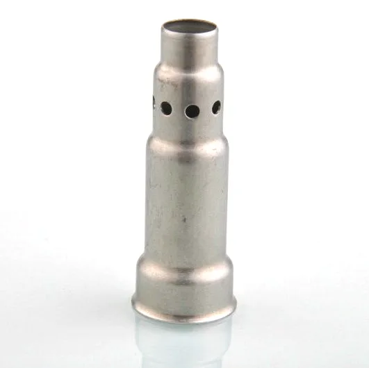
| Item | Stainless Steel Sensor Sleeve with Side Drill Ports |
|---|---|
| Brand | AUNOV |
| Designing | Your drawing sets the part – unusual walls, threads or tolerances are feasibility-checked first; the approved drawing is kept as the controlled master. |
| Tooling | Die design and toolmaking stay in house, so tooling lead time stays under our control, and maintenance is tracked against the part number. |
| Samples | Pre-production samples come with a full inspection report, so the sample is retained as the master, and mass production is gated on that approval. |
| Materials | Carbon steel, 304 / 316 stainless steel, aluminium and brass are all held in stock; mill certificates and heat numbers accompany the first article. |
| Surface finish | Plating, coating or polishing to suit the drawing; the finish is inspected with the dimensional report on the first article. |
| Processing | Drawn shells receive machined seats and threads where the print asks; filed batch records let a repeat order start from approved data. |
| Equipment | Deep drawing presses plus CNC turning centres for machined faces; secondary ops run on CNC turning centres, inspection on the CMM. |
| Tolerance | +/-0.02 mm on machined seats, sealing faces flat to drawing; dimensional reports accompany the first article. |
| Delivery terms | FOB, with DDP offered for EU and US addresses, payment by T/T or L/C, quoted in USD or EUR; price breaks tie to annual volume. |
Related Products


A drawn 304 stainless steel NTC housing has two jobs that pull against each other: it has to be a good thermal conductor between the process and the element, and it has to be a good barrier. Stainless Steel is an excellent barrier and a poor conductor, and that combination is why this housing looks the way it does – thin, drawn, and machined only where the drawing demands it.
So the first question on this part is not dimensional. It is: has the stainless steel been chosen on purpose, and what is the design doing about the conductivity it gives up?
Wall thickness is the sensor’s specification
The wall between the process and the element sets both the response time and the robustness. On a drawn housing it comes from the blank, and it is not uniform, and the non-uniformity is where most of the design questions live.
- The blank’s thickness is the primary specification and it should be called out as a material requirement rather than as a machined dimension. The drawing’s tolerance on the wall should be the blank’s thickness tolerance, and it will be wider than anything else on the part.
- The closed end is thinner than the nominal wall. This is the deep-drawing mechanism: as the blank is drawn, the metal at the punch nose stretches and the closed end becomes the thinnest part of the part. On a sensor housing the closed end is usually exactly where the element sits, so the thinning lands where it matters most. The drawing needs a minimum wall at the closed end, measured there.
- The inside of the corner is thinner than the nominal wall. A drawn corner’s inside radius is the most heavily worked metal on the part, and its effective thickness at the inside of the bend is less than the wall’s nominal. On a housing where the corner carries the seal or the element, that is the number that matters.
- And the machining has to respect all of this. If a machined seat or a counterbore is cut into the drawn wall, the remaining thickness after machining is what the design has to rely on. On a thin housing this is a real constraint and it should be checked rather than assumed.
What stainless steel costs thermally, and what is done about it
Stainless Steel conducts heat roughly twenty times worse than aluminium. That is the number that makes a stainless steel NTC housing a slow sensor, and on many applications that is acceptable – a slower sensor gives a steadier reading. On some it is not acceptable, and the ways out are worth knowing.
- A thinner wall. The most direct answer, and it is limited by the blank’s achievable thickness and by the drawing’s robustness.
- A thermally conductive insert. A copper or aluminium element carrier inside the housing, so the process temperature reaches the element through the insert rather than through the steel. This is a common design in RTDs and in fast-response probes, and it means the housing becomes a mechanical enclosure rather than the thermal path.
- A thermal bead or a thermowell extension. On a measurement where the housing’s mass is a problem, a lighter gauge or a smaller tip changes the response, in the same way that a lighter sensing element does.
- Accept it and specify the response time. On a tank temperature or a slow process this is the correct answer, and the housing’s wall should then be chosen for robustness and for corrosion rather than for response.
So the honest question is whether the response time has been specified. If it has, the wall is a calculated thickness. If it has not, the wall is whatever the drawing process produced, and the sensor’s response is whatever it turns out to be.
304 versus 316L, and the one place the grade changes the product
Carbon steel, 304 and 316 stainless steel, aluminium and brass are held, with mill certificates and heat numbers on the first article. On a temperature sensor the grade is chosen by the process, and there is one consequence of the grade that goes beyond corrosion.
- 304 for clean, dry, low-chloride service. Adequate and the economical choice.
- 316L for anything chloride-bearing, for food or pharmaceutical service, or for a cleaning regime. The chloride in a cleaning agent is often the deciding factor rather than the chloride in the process, and this is worth raising explicitly on a sensor enquiry because nobody thinks about the cleaning regime when they choose the housing.
- The L grade, wherever there is welding. A welded closure on a sensor housing is a common design and 316 rather than 316L risks sensitisation in the weld’s heat-affected zone – a corrosion initiation site inside a housing that will later be exposed to moisture.
- And the thermal difference between the grades is small but real. 304 and 316L differ slightly in thermal conductivity. It is a second-order effect next to the stainless steel-versus-aluminium difference, and it is not a reason to choose between them. It is worth stating that so nobody picks a grade for a thermal reason it cannot deliver.
The sealing face and the closure
+/-0.02 mm on machined seats and sealing faces flat to the drawing. That flatness requirement is the part’s tightest, and it is where the housing’s function is decided.
- A gasketed closure – a gland with an O-ring, or a face with a gasket – needs a flat, parallel, well-finished face, and the face’s perpendicularity to the axis is a separate measurement from its flatness. A face that is not square will seal unevenly around its circumference and that is a leak path on one side.
- A welded closure is a different engineering problem. The weld has to be continuous, leak-tight and hermetic, and its geometry – penetration, absence of inclusions, a smooth transition – is a functional specification. On a hermetically sealed sensor the weld is the product’s reliability, and specifying it as “welded closure” is not enough.
- A press-fit or interference closure depends on the housing’s wall and its elasticity, and on the material’s pairing with the part it presses against. On a thin drawn wall an interference fit risks distorting the wall, and a distorted wall distorts the bore that the element sits in.
On all three, the common requirement is the same: the closing face has to be flat and clean, and it has to be inspected before assembly. A drawing that calls for a sealing face flatness but does not say to what datum and in what condition leaves the measurement open to interpretation.
Plating, coating or polishing, and where it must not go
Plating, coating or polishing to suit the drawing, with the finish inspected with the dimensional report on the first article. On a sensor housing the finish requirement is narrow and it is entirely about the closure.
- The sealing face, unmasked. A plated or coated sealing face will not seal, and there is no argument about it.
- On 304 and 316, passivation is the right treatment and plating is not. Passivation restores the corrosion resistance that drawing and machining removed, and it leaves the geometry alone.
- Where the housing is externally visible – a panel-mounted probe, an instrument housing – the external finish becomes an appearance requirement and an approved sample is the specification. And on a drawn part with a machined band, the drawn surface and the machined surface take a finish differently, so the transition is visible. It is worth deciding that with the finish in mind.
- Laser marking is the sensible identification method on a small housing, because it does not add thickness and does not affect any fit.
Why the machined features are so few
Drawn shell with machined seats and threads where the print calls for them – that phrase carries the whole design philosophy, and the question it raises is which features those are.
- Drawn: everything that does not need a tolerance. The wall, the open diameter, the corner radii, the general shape. All of these are consistent within the material’s own variation and drawing them is inexpensive.
- Machined: everything that seals, locates or threads. Sealing faces, spigots, threads, and any seat that has to be concentric.
- And the design question is whether the machining can be eliminated. On a housing whose only machined features are a sealing face and a thread, it is frequently possible to design the closure so that it is a drawn feature – a rolled rim, a drawn bead, a formed lip – and then the whole part is a drawing operation. That removes the machining cost, the second setup, and the tolerance stack between the drawn features and the machined ones. It is not always possible, and where it is not, the reason should be on the drawing.
What to establish before the quotation
- The response time, and what the sensor is measuring. This sets the wall’s thickness, and it decides whether the stainless steel is the right material at all.
- The process: the fluid, the temperature, the pressure, and the chloride content. Four things that decide the grade.
- The cleaning regime, if the housing is in a food, pharmaceutical or medical application. The chloride in the cleaning agent is often what decides 316L.
- The closure method, and whether it is hermetic. This decides whether the drawing needs a weld specification or a flatness specification, and they are different documents.
- How the sensor is mounted: leads, a terminal, a connector, or a mounting flange. This changes the closure and adds its own sealing requirement around the wire or the connector, which is a separate design problem from the housing’s own seal.
Five answers, and they decide the housing’s material, its wall, its grade, its closure, its process route and its test. None of them needs a drawing, and every one of them changes what the part is.
Related Products


Frequently Asked Questions
Why does this housing have two jobs that pull against each other?
It has to be a good thermal conductor between the process and the element, and a good barrier at the same time. Stainless steel is an excellent barrier and a poor conductor, and that is why the housing looks the way it does: thin, drawn, and machined only where the drawing demands it. Stainless steel conducts heat roughly twenty times worse than aluminium.
Has the stainless steel been chosen on purpose?
That is the question to ask, because the design has to be doing something about the conductivity it gives up. On many applications a slower sensor gives a steadier reading, so the poor conduction is acceptable. Carbon steel, 304 and 316 stainless steel, aluminium and brass are held, with mill certificates and heat numbers on the first article.
Where does 304 versus 316L actually change the product?
The grade changes the product in one place, the corrosion duty of the fluid, beyond which the thermal argument is the same. Wall thickness is the sensor’s specification, and it is kept thin to shorten the thermal path. Drawn shell with machined seats and threads where the print calls for them runs at +/-0.02 mm on machined seats and sealing faces flat to the drawing.
Why are the machined features so few?
Because the wall is the accuracy and machining it only where the drawing demands it keeps the thermal path short and the cost down. Plating, coating or polishing is to suit the drawing, with the finish inspected with the dimensional report on the first article, and where it must not go is the thermal face. What to establish before the quotation is whether that thin wall is acceptable for the process pressure.
Request a Quote for This Part
Send a drawing or sketch — get material advice, tooling cost and a per-piece price within 24 hours (working days).