
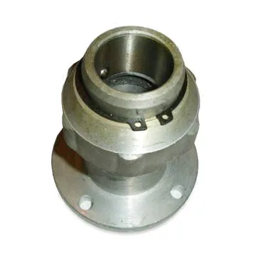
A three-piece flare fitting makes its seal by deforming the tube, and it does so in two stages: a first flare that forms the tube into a cone, and a second that presses that cone against the fitting’s seat. That two-stage process is why there are three pieces, and it is also why this fitting has a requirement that no compression or threaded fitting has: the tube must be flareable, and the flare must be made to the fitting’s seat rather than to a nominal angle.
The three pieces are the body, the nut, and the flare itself – the third piece is the tube. And that is the part that makes the assembly’s reliability somebody else’s problem.
Why three pieces, and what each one is doing
- The body carries the port, the seat that the flare seals against, and the threaded or tapered end. It is the only part with any real geometry and the only part whose dimensions are hard to hold.
- The nut draws the flare onto the seat. It is a simple part geometrically, and it has two requirements that are easy to miss: it has to be strong enough to develop the assembly torque without deforming, and its thread has to be capable of being run down onto the body’s thread many times without galling.
- The tube’s flare is the seal. It is made by a flaring tool, and its geometry – its angle, its length, and especially its face – is what determines whether the fitting seals.
And that third member is the one that is not machined by the fitting’s supplier. It is made on site, by the person assembling the system, with a hand tool or a hydraulic flarer, and its quality is the single largest variable in whether the fitting works. Every design decision on this fitting is downstream of that fact.
The flare’s geometry, which is the seal
A flare is a cone with a face. Three properties, all of them functional, and all of them produced by the flaring tool rather than by the fitting.
- The cone’s angle, which must match the seat’s angle. This is a matched pair and it is the most common reason a flare fitting weeps: a flare made to a nominal angle that does not match the fitting’s actual seat. The tolerance on the flare’s angle is not something the fitting’s supplier controls, so the seat’s angle must be held tightly and the assembly instruction must specify the flaring tool’s setting.
- The flare’s face, which is the flat annular surface that seals against the fitting’s face. Its width has to be within limits – too narrow and it will not seal reliably, too wide and the tube has insufficient material and the flare will crack. Its flatness and its perpendicularity to the tube are what distribute the seal’s pressure.
- The flare’s length, which has to be long enough to give the flare’s full strength and short enough that it does not bottom out in the fitting. A flare that is too long will bottom out in the seat before the nut is properly tight, and then tightening the nut further does nothing except load the tube.
So on this part the requirement that carries the most weight is the simplest one: the body must be designed to the flare tool that will actually be used on site. A fitting designed for a standard flaring tool and assembled with a cheap hand flarer on a worn die is a fitting that leaks, and no amount of tolerance on the fitting will fix it.
The tube, and its wall thickness is the whole story
As with a compression fitting, the tube’s wall thickness range decides whether the flare will form properly, and the failure mode is a split.
- A tube that is too thick for the flare cannot form the required geometry without exceeding the material’s strain limit, and it will split at the flare – usually at the root of the flare, or at the transition between the flared and unflared sections.
- A tube that is too thin forms easily but has insufficient material for the flare’s face, so the face is narrow and the seal is poor and the flare may deform during tightening.
- The split is not visible immediately. A tube that has cracked at the flare’s root may pass a pressure test for a while and then fail, and the failure mode is a sudden loss of pressure rather than a slow weep. This is why a pressure test immediately after assembly is worth doing on a flare connection.
- The tube’s material and temper matter too. A hard copper tube flares differently from a soft one, and a thin-wall stainless steel tube requires a different flaring process entirely – and on stainless steel, work hardening during flaring means the flare can be formed but will crack at the edges if the process is wrong.
So the specification should name the tube standard, its wall thickness with a tolerance, and its temper or condition. A flare fitting specified only by nominal size is roughly half specified, and the missing half is what determines whether it works.
The seat, which is the body’s hard feature
The body’s sealing face is the hardest functional feature on this part, and it has three requirements.
- Flatness. The flare’s face is a flat annular surface and it has to seal against a flat surface. Any deviation means the seal’s pressure is concentrated on the high points and the seal is uneven. This is a genuine flatness requirement, not a general note.
- Perpendicularity of the seat face to the body’s axis, independently of the face’s flatness. A face that is not square to the axis will seal unevenly around its circumference.
- The seat’s angle, matched to the flare’s angle, held tightly enough that the pairing is reliable across a production lot.
- The seat’s internal radius at the bottom of the cone, which is where the flare’s nose sits. A sharp internal corner here will cut the flare’s nose during assembly and will create a leak path, and a generous radius there is the standard detail on a good fitting.
The nut, and the two things that go wrong with it
- The nut’s strength. It has to develop the assembly torque without deforming, because a deformed nut’s flats will not run down again and the fitting will have to be cut off. On a small fitting this is a real design requirement, and it is a function of the nut’s height and the material’s yield.
- The nut’s thread galling against the body’s thread. On stainless steel this is the dominant practical problem on the whole part. A stainless steel nut on a stainless steel body, tightened and then loosened, will gall. The remedies are the standard ones – a dry film lubricant, a dissimilar grade pairing, a defined break-loose torque – and on this part one of them is specific: many flare fitting designs use the nut to make the connection and the connection is made once, which reduces the galling exposure. Where it will be disconnected repeatedly, it is a genuine design issue.
- The nut’s length, which determines how far the flare can advance into the seat and therefore how much the flare is compressed. This is a real geometric relationship and it is a design output rather than a detail.
A flare fitting has to agree with the tube it connects to
Materials held include carbon steel, 304 and 316 stainless steel, aluminium and brass, with the final grade fixed at the drawing review. On a flare fitting the material decisions are more consequential than on most, for two reasons.
- The fitting and the tube must be compatible. A stainless steel fitting on a copper tube is a galvanic couple in a wet connection, and on a flare fitting the couple exists in the region where the fluid sits. This is a normal consequence of choosing stainless steel for a fitting that will see copper tube, and it is worth accepting explicitly rather than by default.
- 316L is the normal stainless steel answer, on the chloride logic.
- Brass is the traditional flare fitting material and it is still very widely used, because it forms well, it is easy to machine to the seat’s geometry, and it deforms rather than cracks. Its limitation is dezincification in a wet service.
- Carbon steel is used where the service is benign, with a plating, and the plating has a specific consequence on this part: it must be masked off the seat, because a plated seat changes the angle and the flatness of the surface the flare seals against, and the plating will not hold the flare’s face properly.
- Aluminium appears on hydraulic and pneumatic lines where a flare fitting is used, and it is workable. But aluminium flare fittings on steel or copper systems create couples, and aluminium’s low strength limits the nut’s torque.
The seat must be left bare, and the finish chosen around that
Zinc, nickel or chrome plating, anodising, passivation or e-coat, with masking and laser marking available. On this part the finish requirement is unusually specific and it is the same requirement as on a compression fitting’s ferrule seat.
- The seat must be unmasked. It is a sealing surface and a plated or anodised seat will not seal reliably against a copper flare. This is the single most important masking item on the part.
- On stainless steel, passivation is the answer and plating is not – for the corrosion resistance, for the thread, and because a plated stainless steel flare fitting’s seat is a problem.
- The body’s threads – masked, or specified post-plate with an allowance. On a small flare fitting the thread’s plating is a meaningful fraction of the pitch.
- The nut is often plated for appearance, and the plating’s effect on the nut’s thread’s fit has to be in the allowance.
- Laser marking is a sensible identification method here because it does not affect the thread, the seat or any fit, which a stamped mark on a small fitting body would.
On a flare fitting the seat needs more than the thread does
+/-0.01 mm on ground diameters, GD&T from the print, capability checked on the first article. On a flare fitting the flagged dimensions are the seat and the thread, and the seat needs more than the thread.
- The seat’s angle, flatness and perpendicularity, as a group. This is the part’s most important dimensional set and it is normally specified loosely.
- The seat’s diameter and its position along the axis, because the flare’s advance and therefore the sealing depends on both.
- The body’s thread class and pitch diameter, gauged, and stated pre- or post-finish.
- The nut’s thread, gauged, and its width across flats as a wrench fit.
- The bore’s diameter and its position relative to the seat, because a misalignment between the bore and the seat axis will produce an uneven flare.
- General dimensions at a general band, including the body’s length, which is a general coordination dimension with the tube.
Test the flare your customer will make, not the one in the lab
- The seat’s angle, flatness and perpendicularity on every part – the same item as above, and it cannot be sampled because it is the seal.
- A functional leak test, and specifically a test that includes a flare made by the flaring method that will be used in service. A fitting tested against a laboratory-made flare is not the same product as one assembled on site.
- Thread gauging on the body and on the nut, every part.
- The nut’s width across flats and its strength to the assembly torque – the torque check is quick and it confirms the nut will not deform.
- CMM data on the flagged dimensions, with batch records filed so a repeat order starts from approved data.
- Finishing thickness and adhesion on the first article, with the masked seat and threads verified.
The flaring tool, and the tube standard
What flaring tool will be used on site, and what tube standard and wall thickness will be used? Those two answers decide whether this fitting works, and they are the two that are most often missing. A fitting designed against a standard flaring tool is a good fitting; the same fitting assembled with a worn hand flarer on a thin-wall tube will split the tube at the flare’s root and leak, and no tolerance on the fitting is relevant to that. So it is worth stating the tube standard and wall thickness with its tolerance, and it is worth stating whether the flaring will be done by hand or by a hydraulic flarer, and whether the same flaring specification applies at every assembly point or only at some. On a hydraulic or a pneumatic system where the same tube is flared at many points, the consistency of the flaring process matters more than the consistency of the fittings, and it is worth saying so on the assembly drawing. A flare fitting is one of the very few components whose success depends on a third party’s workmanship on a part the fitting’s supplier does not make.
CNC Machining Parts is the parent range for parts like this one; the overview page gathers the tooling logic, finishing options and tolerance notes that apply across the family.
Specifications
| Item | Stainless Steel 3-Piece Flare Fitting |
|---|---|
| Brand | AUNOV |
| Designing | Your drawing sets the part – unusual walls, threads or tolerances are feasibility-checked first; the agreed version governs every later batch. |
| Tooling | Die design and toolmaking stay in house, so the die charge appears as its own quotation line, and maintenance is tracked against the part number. |
| Samples | Samples are issued for approval before the run, so the part is proven before it is made in volume, and production starts only after your written sign-off. |
| Materials | Materials held include carbon steel, 304 / 316 stainless steel, aluminium and brass; the final grade is fixed with the drawing review. |
| Surface finish | Zinc, nickel or chrome plating, anodising, passivation or e-coat; masking and laser marking available where needed. |
| Processing | Bar-fed turning with milled features completed in the same clamping; batch records are filed so a repeat order starts from approved data. |
| Equipment | 12 CNC turning centres with automatic bar feeders; secondary ops run on CNC turning centres, inspection on the CMM. |
| Tolerance | +/-0.01 mm on ground diameters, with GD&T taken from your print; capability is checked on the first article before the run continues. |
| Delivery terms | FOB, with DDP offered for EU and US addresses, T/T or L/C, with D/P accepted on repeat business; each volume tier carries its own quoted price. |
Related Products



Request a Quote for This Part
Send a drawing or sketch — get material advice, tooling cost and a per-piece price within 24 hours (working days).