
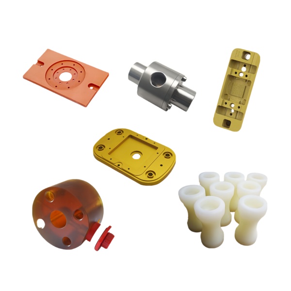
Anodize layer thickness is not decorative—it changes the bore size and the press-fit tolerance
When a machined aluminum plate receives a Type II or Type III anodize coating, the coating grows both outward from the original surface and inward by consuming base metal at roughly a 1:1 ratio. A 25 µm (Type II) coating therefore removes about 12–13 µm of base material from every surface it covers. On a plate with a 10H7 bore (nominal 10.000 mm, tolerance +0.015/0), that means the as-anodized bore diameter shrinks by 0.024–0.026 mm total—enough to convert a smooth sliding fit into an interference fit if the mating pin was ground to the nominal size.
This is not a theoretical concern. We routinely receive customer drawings for anodized aluminum plates that specify the bore size in its final-as-anodized state but do not specify whether the dimension applies before or after coating. Our standard practice is to machine the bore 0.025 mm oversize per side for Type II and 0.040 mm oversize per side for hard coat (Type III), then verify the post-anodize diameter with a go/no-go plug gauge before shipping. If the drawing explicitly calls out pre-plate dimensions, we follow that and note it on the inspection report; if it is ambiguous, we add a drawing note calling out the as-anodized condition and proceed with the oversize approach.
Nylon spacer compression set under long-term clamp load is what causes bolt loosening
The nylon spacers that often accompany these aluminum plates are there to provide electrical insulation, vibration damping, or corrosion isolation between the plate and its mounting surface. Nylon 6/6 in its unreinforced form has a compressive yield strength of about 70 MPa at room temperature, but it creeps continuously under sustained loads above 20 % of that value. A M5 bolt tightened to 4 N·m produces roughly 2,000 N of clamping force; distributed over a 10 mm OD × 5 mm ID nylon washer, that is 34 MPa of bearing stress—well into the creep regime.
Over 6 months of continuous operation at 60 °C (typical under-hood or near-motor temperature), that same spacer will experience 8–12 % permanent compression set, which translates to 0.04–0.06 mm of thickness loss. If the bolt was not re-torqued after the initial break-in period, the clamping force drops by 15–25 % and the joint begins to micro-slip. The solution is not to switch to a stiffer material (which transfers more vibration to the plate and can cause fatigue cracking at the bore edge) but to specify a glass-filled nylon (PA66-GF30%) that reduces creep strain by roughly 60 % at the same stress level, or to design the joint with a conical seat that converts some of the axial compression into radial confinement, slowing the creep rate.
Flatness tolerance on the mounting face determines whether the plate bends when bolted down
A machined aluminum plate that measures flat within 0.05 mm over a 100 × 50 mm footprint in the free state can easily distort to 0.2–0.3 mm out-of-flat when clamped at its four corners to a casting that itself has 0.1 mm of local waviness. The distortion comes from forcing the plate to conform to the mating surface, inducing bending stresses that may exceed the elastic limit of the 6061-T6 material (276 MPa yield) in the regions between fasteners.
Once the plate yields plastically, it never returns to its original shape even after unbolting. This is why we specify a maximum clamping-induced bow of 0.10 mm for any plate that carries a shaft or bearing bore within 20 mm of the mounting plane. To guarantee this, we either (a) grind the mounting faces after machining to achieve 0.02 mm flatness, which leaves enough margin to absorb mating-surface error, or (b) add a relieved pocket around each bolt hole so that the clamping force is applied through a shoulder rather than across the full face. Option (b) adds about 30 seconds of milling time but eliminates the flatness problem entirely for plates thicker than 6 mm.
Bore-to-face perpendicularity matters more than bore parallelism for single-shaft plates
On a plate that supports a single rotating shaft, the critical geometric relationship is not the parallelism between two bores (there is only one) but the perpendicularity between the bore axis and the mounting face. A perpendicularity error of 0.05 mm over a 15 mm projection length translates to a shaft angular misalignment of 3.3 mrad (0.19°). At a shaft speed of 3000 rpm with a 20 mm bearing span, that misalignment increases the dynamic load on the bearing by roughly 15–20 % compared to the perfectly aligned case, reducing L10 bearing life by 30–40 %.
We hold bore-to-face perpendicularity to 0.02 mm TIR at the outer diameter of the bore projection. This is verified on every part by placing the mounting face on a granite surface plate and running a dial indicator around the bore ID at the top of the projection. Parts that exceed 0.02 mm are re-clamped and lightly bored (removal stock of 0.05 mm max) to correct the angle. This operation sounds expensive but averages less than 90 seconds per part because the correction cut is tiny and the tool path is pre-programmed for the specific error direction.
Edge chamfer quality on the bore prevents damage to seals during assembly
When a shaft seal (oil ring, O-ring, or lip seal) is pressed through a bore during assembly, the lead-in chamfer is the only thing preventing the seal lip from being cut or folded over. A sharp 90° edge or a broken chamfer with burrs will nick the seal on the first installation attempt, creating a leak path that may not show up until the equipment has run for 50–100 hours—long after the assembly department has signed off on the build.
We specify a minimum 0.3 mm × 45° chamfer on all bores that will see seal installation, and we inspect it with a profile projector at 20× magnification on the first article and then at SPC intervals of every 50 parts. The chamfer must be free of visible burrs and must have a consistent angle; a “ragged” chamfer that varies between 20° and 60° around the circumference is actually worse than no chamfer at all because it concentrates the seal contact stress at the transition points. For bores below 8 mm where a cutting-tool chamfer is difficult to control, we use a drag-finishing pass with a abrasive-impregnated brush that produces a radiused entry (R0.2–R0.3 mm) which is gentler on seals than any machined chamfer.
How we confirm the anodize layer does not flake at bore edges under press-fit
The junction between the anodize coating and the bare aluminum at a bore edge is a natural stress concentrator. When a bushing or bearing is pressed into that bore, the coating at the edge is subjected to peeling forces that can cause it to delaminate in flakes. Those flakes then become abrasive particles in the interface, scoring the bearing outer race and generating noise and wear.
We perform a press-fit test on one sample per batch (one per 200 parts) using a master pin at the maximum material condition of the mating component. After pressing, we examine the bore edge at 30× magnification for any sign of coating lift or flaking. If flaking is observed, we introduce a mask-and-anodize process where the bore is plugged with a silicone mandrel during anodizing, leaving the bore surface uncoated. The bore is then treated with a chemical conversion coating (Alodine 1200s) that provides corrosion protection without building up thickness. This adds about 0.03 USD per part in material and labor but eliminates the flaking mode entirely for interference fits above 0.01 mm.
Parts like this one sit under the CNC Machining Parts range, whose overview page gathers the tooling logic, finishing options and tolerance notes shared across the family.
Specifications
| Item | Anodized Aluminum Machined Plates with Nylon Spacers |
|---|---|
| Brand | AUNOV |
| Designing | Send drawings, or send a spacer sample to be measured, you get a DFM review together with the quotation. |
| Tooling | Every die designed and built in our toolroom, held under your part number. |
| Samples | Sample parts arrive with a full dimensional report and mill certificate. |
| Materials | Stock for this part leads with aluminium, alongside carbon steel (SPCC / DC01), 304 / 316 stainless steel, brass and copper, per the drawing. |
| Surface finish | Plating, e-coat, powder coating, anodising or passivation as the drawing calls out, per your print. |
| Processing | Progressive deep draw stages with in-line annealing as the draw ratio demands, then pierced and machined in house. |
| Equipment | Mechanical presses 5-250 T and hydraulic presses 250-500 T, CNC cells plus a temperature-controlled CMM room. |
| Tolerance | Drawn tolerances held to +/-0.1 mm, +/-0.03 mm after machining. |
| Delivery terms | FOB is standard; DDP offered for EU and US, payment T/T or L/C, D/P for repeat accounts, call-off scheduling supported. |
Related Products


Request a Quote for This Part
Send a drawing or sketch — get material advice, tooling cost and a per-piece price within 24 hours (working days).