
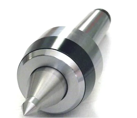
A tapered tool holder with a cone tip is a precision part in a way that its size suggests it is not, because everything about it is a mating surface and the whole assembly – the machine’s spindle taper, the holder, the cutting tool – is held together by a fit that is deliberately not zero. That deliberate gap is the single most misunderstood thing about taper fits, and almost every tool holder problem traces back to it.
The rule that governs the entire subject is simple and worth stating first: a taper fit is not an interference fit. It is a controlled clearance that becomes a holding force only when the taper is clamped axially.
Why the taper needs a clearance, and how it holds anyway
A tapered shank in a tapered bore makes contact in a ring. If the two cones are exactly parallel and exactly the same angle, the contact is a circle and it holds nothing. The holding comes from the fact that a very slightly different angle means the two cones touch at one point on one side of the diameter and touch at three points spread around the other side.
That is a real phenomenon and it has real consequences:
- The contact pattern is three points, not a circle. Three points define a plane and therefore a centre. That is where the holder’s centre is set, and it is why a clean taper fit will hold on the centreline without any interference at the back.
- The axial pull is the real load. The cone’s axial holding force is a direct consequence of the friction at the contact points and of the cone’s angle. For a typical tool taper the friction coefficient on clean ground steel is around 0.1 to 0.15, and that gives a holding strength several times the tool’s weight and a significant multiple of the cutting force. But it is a friction system, so anything that reduces the friction reduces the holding.
- Therefore cleanliness and cleanliness matter more than tolerance. The most common cause of a tool pulling out is a chip, a burr, or a smear on the taper – and not a dimensional error at all. A single chip trapped on the cone reduces the contact at that point, shifts the three-point pattern, and can cut the holding force by half.
- Therefore oil on the taper is a decision, not an accident. Oil reduces the friction coefficient and therefore the holding. This is why spindle tapers are cleaned before assembly and why some machine shops deliberately avoid oiling a taper. It is also why a taper assembly that has been oiled may not hold and why an arbor with an oil groove exists – to deliberately control where the oil is.
The taper angle, and why it is standardised
Taper angles are standardised so that the machine’s spindle and the holder are interchangeable, and this is worth understanding because it explains a lot about the design.
- A steeper taper gives more holding force per unit of axial movement, because the friction is resolved more directly against the taper’s axis. A shallower taper gives less holding but is more tolerant of dirt and less likely to be damaged.
- Standard angles exist for a practical reason: the taper has to be short enough to fit in a spindle and long enough to develop the contact pattern, and the axial movement needed to seat the cone has to be small enough that the tool change is quick and the draw force is manageable.
- The taper’s angle tolerance and the spindle’s angle tolerance both matter and they interact. A holder with a slightly steeper angle than its spindle will seat at one diameter; a holder with a shallower angle will seat at a different diameter. This is why a taper is not interchangeable unless both angles are within their bands, and why a worn spindle’s replacement is not just a dimensional question.
And there is one specific and commonly-missed item: the taper’s angle must be measured over its full length. A cone that is right at one end and wrong at the other will seat on a circle at the wrong end and will not develop a proper three-point pattern. On a small holder the angle measurement is a contact or an optical measurement at several positions, and it is a real inspection item rather than a general note.
The end face, which is a second functional surface
On a tool holder, the shank’s end face – the back of the cone – is the reference surface for the tool’s axial position. This is often overlooked and it is functionally important.
- Flatness and perpendicularity of the back face to the taper axis. The tool’s projection is measured from this face. If the face is not square, the tool will project differently at different points around the cutter’s diameter, which on a peripheral cutting edge means a varying cutting depth and a chatter-prone cut.
- Cleanliness of the back face. The same applies as on the cone: a chip trapped under the tool or on the back face changes the tool’s projection and reduces the hold.
- Whether the design should have an end relief. Many tool tapers have a relieved back so that the holder seats without the shank’s end face having to be perfectly ground against the spindle’s face. Where the spindle has a swarf groove or a relief, the holder’s design must accommodate it.
The retention mechanism, which is part of the part
How the tool is retained in the holder is a design decision with a direct consequence for the holder’s geometry.
- A drawbar through a threaded bore in the holder – the tool is pulled into the taper by a drawbar that hooks the tool’s shank. This means the holder needs a threaded bore at its centre, which means the centre of the holder is weakened and, more importantly, that the holder’s bore must be long enough to reach the drawbar’s hook. A holder designed for a pull stud and used with a different retention method will not work.
- A side lock or a button lock – the clamp pushes from the side. This is common on smaller holders and it does not need a central bore. Its consequence is that the clamp’s geometry affects the shank’s seating, and a side-clamp design has a specific sensitivity to the clamp’s condition.
- A collet or a sleeve – a collet in the taper rather than the tool directly. This changes the taper’s duty entirely: the collet is now the precision surface and the holder is the taper. On a machine with a collet system, the holder is a much simpler part and the precision moves to the collet.
So the retention method should be stated on the holder’s drawing. It determines the holder’s central geometry, it determines what the holder is compatible with, and it determines whether the tool shank or a collet is the precision interface.
Material, and the specific consequence for a tool holder
Carbon steel, 304 and 316 stainless steel, aluminium, brass and copper, with the grade matched to the duty. On a tool holder, the material choice is dominated by one requirement: the taper has to remain dimensionally stable, and it has to be dimensionally stable in a way that does not change the fit.
- Case-hardened carbon or alloy steel is the standard answer. The taper is case-hardened to resist wear and to hold its size, and the core remains tough so the holder does not shatter. This is the conventional material and it is correct for a production tool holder.
- Stainless Steel is used where corrosion matters, and it is a poorer choice for a taper than it might appear. It galls readily against a cast iron or steel spindle, it work-hardens, and a galling or work-hardened taper will pick up on the spindle and become hard to clean. It is a specialist choice.
- Aluminium is used where the holder’s own mass matters or where thermal conductivity is wanted, and it is a legitimate answer for a light-duty or a high-speed holder. Its problem on a taper is thermal: aluminium’s expansion coefficient is roughly double that of steel, so a holder that is steel-tapered and aluminium-bodied needs a thermal design, and an all-aluminium holder expands enough between the machine’s cold start and warm running to lose its grip.
- Brass and copper appear where a non-sparking requirement exists or where a holder must not mark the spindle. They are soft, they wear, and they are not for a production tool holder.
Surface finish, and here it is not cosmetic at all
Plating, powder coating, anodising or polishing per the print, with finish thickness and adhesion checked on the first article. On a tool holder the finish is one of the most important things on the part, and there is a hard rule:
- The taper must not be plated, coated, anodised, or polished to a bright finish. Each of those destroys the fit, and in the same three ways: a coating changes the size and therefore the seating; a polished surface reduces the friction and therefore the holding; and most importantly, a plated or coated taper will not seat properly against a clean steel spindle because the coating’s thickness varies and the contact will not be a three-point pattern.
- The taper is ground, not finished. A ground taper has a specific surface – fine, directional, matte – and it is what produces the correct contact pattern and the correct friction. The finish of a taper is part of its specification and it should be stated.
- Where the holder’s body is plated or coated for corrosion or appearance, the masking of the taper is the critical requirement. A plating run that does not fully mask the taper is a rejected batch.
- The rest of the holder’s finish is largely practical – corrosion protection and appearance – and is where the approved sample and the adhesion test come in.
Tolerance, allocated to the fit and nothing else
+/-0.01 mm on turned and milled features, GD&T per drawing, PPAP-style reports on request. On a tool holder the flagged dimensions are all about the taper and its relationship to the tool.
- The taper’s angle, measured over its full length, with a tolerance on the angle itself and a requirement about where it is measured.
- The taper’s size – its major diameter – with a tolerance, and it should be stated whether it is before or after any finish, though on a taper the answer is that it is not finished.
- The taper’s roundness and cylindricity. On a taper this is what makes the contact pattern a clean three points rather than a smeared band. A taper that is out of round will contact along a band and will hold less and mark the spindle.
- Axial position of the taper’s reference end face to the tool bore’s shoulder or to the holder’s front face, because this sets the tool’s projection.
- Parallelism and perpendicularity of the tool bore to the taper axis, and concentricity of the bore to the taper. A holder whose bore is off-centre relative to its taper will have the tool’s cutting edge not aligned with the holder’s centre, which will produce a cut that varies around the cutter.
- The clearance bore for the tool shank, and its fit to the tool. This is a second fit on the same part and it deserves the same discipline as the first.
- Everything else at the general band.
A two-point micrometer check cannot qualify a first-article taper
- Taper angle, by an instrument that measures it over the taper, at several positions along the length. A micrometer-based check of the taper’s diameter at two points gives a crude angle, which is adequate for acceptance on a production holder and entirely inadequate for a first article.
- Taper roundness and cylindricity, which is a distinct measurement from the taper’s size.
- A functional fit check in the machine’s spindle, on the first article. This is the only inspection that tests the actual requirement – that the holder holds – and it takes minutes. It should include a check that the holder does not creep under the spindle’s own draw force.
- Spindle condition verification, before the holder is accepted. A holder that measures perfectly and does not hold is usually a spindle problem, and this needs to be established before the holder is blamed.
- The tool bore’s concentricity to the taper and the bore’s size, on the CMM.
- PPAP-style reports on request, which on a tool holder is worth having for a different reason than usual: the data makes it possible to argue about whether a spindle or a holder is responsible when a tool pulls out in service, and that argument is expensive.
Drawbar, side lock, or collet
Which retention method does this holder use – a drawbar, a side lock, or a collet? And is this holder’s taper going to be the precision interface, or will a collet be? These two questions determine the holder’s central geometry, its compatibility, whether it needs a drawbar hole, what its tolerance priorities are, and whether the tool shank or the collet is the part that needs the accuracy. They also determine something that is surprisingly often a problem in practice: whether the holder is interchangeable with the machine’s existing tooling. A tapered holder drawn to a standard taper angle is not automatically compatible – the taper’s size, the class of fit, the retention, and the draw force all have to match what the spindle expects. Getting this right at enquiry stage costs two sentences and it prevents the most common class of error on this part, which is a perfectly good holder that does not work in the machine.
This part belongs to our CNC Machining Parts range. The cnc machining parts pages collect the process notes, common materials and inspection points behind every product in the family.
Specifications
| Item | Steel Tapered Tool Holder with Cone Tip |
|---|---|
| Brand | AUNOV |
| Designing | Send drawings, or send a sample to be measured – samples are reverse-measured into a controlled drawing; the approved drawing is kept as the controlled master. |
| Tooling | Our toolroom covers die design, wire-cut EDM and maintenance, so no tooling step is outsourced, and ownership is confirmed on the quotation. |
| Samples | Samples are issued for approval before the run, and production starts only after written sign-off. |
| Materials | Carbon steel (SPCC / DC01), 304 / 316 stainless steel, aluminium, brass and copper – the grade is matched to the duty of this holder. |
| Surface finish | Plating, powder coating, anodising or polishing, per the print; finish thickness and adhesion checked on the first article. |
| Processing | Bar-fed turning with milled features completed in the same clamping; batch records are filed so a repeat order starts from approved data. |
| Equipment | CNC turning centres with bar feeders and 3-/4-axis machining centres, with CNC turning centres for secondary operations and CMM inspection. |
| Tolerance | +/-0.01 mm on turned and milled features; GD&T per drawing, PPAP-style reports on request. |
| Delivery terms | FOB, CIF or DDP per Incoterms 2020, payment by T/T, L/C at sight or D/P; price breaks tie to annual volume. |
Related Products



Request a Quote for This Part
Send a drawing or sketch — get material advice, tooling cost and a per-piece price within 24 hours (working days).