
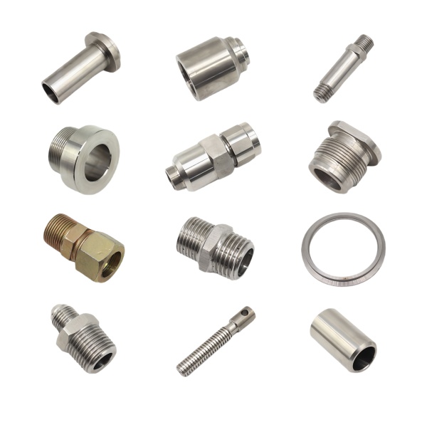
The Assorted Aluminum and Brass CNC Turned Fittings and Pins family lives in the small-diameter, high-count regime where the lathe is the right machine and the details that decide quality are the ones invisible on the drawing: the brass’s lead content, the thread class on a sealing fitting, the stress left in a thin wall by the last cut. This page covers why lead-free brass changes the cutting process, how thread class actually creates a seal on a turned fitting, how thin walls are kept round, and what verification a batch of mixed brass and aluminium parts ships with.
Lead-free brass changes the tool edge and the thread crest
Free-machining brasses such as C36000 carry around 3% lead, which exists in the microstructure as tiny particles that act as internal lubricant and chip breakers – they are the reason brass historically machined twice as fast as steel at a fraction of the tool wear. Regulatory pressure has moved much of the industry to lead-free grades, and those grades machine differently in ways that show up directly on small turned fittings: chips run long and stringy instead of breaking, cutting temperatures rise, tool life drops, and thread crests tear instead of shearing cleanly. A fitting program written for C360 and run unchanged on lead-free stock produces burrs at the thread runout and a surface finish that fails a close look.
- On lead-free brass we run sharper geometry, higher feeds rather than higher speeds, and a chip-breaker form that would be unnecessary in leaded stock – the process window is real, and it is documented in the program under the material grade.
- Thread cutting gets specific attention: a torn crest on a sealing thread is a leak path, so the threading pass uses a fresh edge and a supported cut, and the first thread on the first article is inspected under magnification before the batch runs.
- We ask for the brass grade at quotation rather than assuming it, because the difference between leaded and lead-free is a cycle time and tooling cost difference the customer is already paying in one direction or the other.
- Where a customer specifies both grades as acceptable alternates, we treat them as two different processes that happen to share a drawing.
On a sealing fitting, the thread class is part of the seal
A tapered-thread fitting seals on the thread flanks themselves: the taper forces the flanks into contact as the joint tightens, and whether that contact is continuous around the circumference is decided by thread class, flank angle and diameter control within the class. A class 2A part at the loose end of its band wound into a class 2B hole at the loose end of its band may need an extra turn to seat and still seal imperfectly at the crest roots. Parallel-thread fittings move the sealing duty to a face or an O-ring, and there the thread’s job is clamp force: the thread must be cut accurately enough to bottom the face, because a thread that bottoms first leaves the face dry.
The controls we apply:
- Thread class is verified with go/no-go gauges on the first article and on the agreed sampling plan in production – a fit gauge answers the assembly question, but it does not measure the thread, so first articles get the pitch diameter measured, not just gauged.
- Sealing faces on parallel fittings are machined in the same setup as the thread, so face squareness to the thread axis is generated rather than checked – squareness here is what decides whether the face seal loads evenly.
- Tapered threads get the gauge engagement count recorded: how many turns from hand-tight to the gauge line is the number the installer will feel, and drift in that count is drift in the thread.
- Burrs at the thread runout are removed before gauging, because a gauged thread with a rolled burr passes the gauge and cuts the mating seal on installation.
Thin walls on small fittings are round only if the last cut cooperates
Small fittings frequently have thin sections between bore and wrench flats, and thin-walled turned parts have a specific failure: cut round, unclamp, and measure oval. The collet clamping force alone is enough to make a 0.5 mm wall triangular while it is being cut, and the part springs back to something rounder but not truly round when released. Machining the bore after the outside, or vice versa, changes which form of the distortion survives into the finished part.
- We sequence so that the final operation on a thin wall is the one with the least clamping distortion – bored while held on a machined diameter with soft jaws, or finish-turned on a mandrel where the geometry allows.
- Bar stress contributes: brass and aluminium bar carry drawing stress that releases as the wall thins, so roughing the wall to near-final thickness, letting the part relax, then finishing light, keeps the roundness where full-depth single-pass cutting would not.
- Wall thickness is checked at defined clock positions on the first article, because ovality hides from a two-point diameter measurement and appears the moment the customer bores or seals against it.
- Where the print’s roundness expectation exceeds what the wall can physically hold under clamping, we say so at quotation and propose the mandrel route or a revised clamping scheme rather than ship borderline parts.
Running brass and aluminium in one release rewards planning, not optimism
This family mixes brass and aluminium in a single kitted shipment, and the two materials disagree about tooling: aluminium wants sharp positive edges and high speed, brass runs well with neutral geometry at moderate speed, and an edge optimized for one is mediocre on the other. Changeovers between materials are therefore scheduled as their own events with insert swaps audited against the setup sheet, because the costliest defect in a mixed run is not scrap – it is a finish or a burr defect that passes a glance inspection and surfaces at the customer’s assembly.
- Chip streams are segregated: brass swarf has resale value and aluminium swarf contaminates it, and mixed bins cost money both directions.
- Aluminium parts destined for anodizing get their thread and bore allowances planned with the film, exactly as on any anodized machined part, while the brass side gets nothing but a clean deburr – the release record keeps the two finishing routes straight under one part-number tree.
- Quantity ratios are planned at kit level, so the fast-running aluminium pins and the slower brass fittings arrive balanced against the customer’s call-off rather than as two unrelated batches.
How we verify thread class and seal faces on turned fittings
Verification on this family concentrates on the features that decide whether a fitting seals and assembles. Each release ships with:
- Thread evidence – pitch diameter measured on the first article, go/no-go gauging per the sampling plan in production, and gauge engagement counts recorded for tapered threads.
- Seal face condition – finish and squareness verified on the first article with the report stating Ra values on sealing faces, not adjectives.
- Bore and port geometry on flow-critical fittings measured at stations, so taper and ovality appear as numbers.
- Edge condition sampled under magnification against the edge criterion in the control plan, with particular attention to thread runout and cross-hole intersections.
- Kit reconciliation at packing: brass and aluminium component counts against the kit BOM, with heats and lot numbers for both material streams recorded in the release.
- First-article archive under the part number with material certificates, so repeat orders inherit the verified setup rather than a re-invention of it.
The result is a mixed-material release the customer can feed to the line without sorting, with the dimensional and thread evidence to explain any question that arises months later.
Parts like this one sit under the CNC Machining Parts range, whose overview page gathers the tooling logic, finishing options and tolerance notes shared across the family.
Specifications
| Item | Assorted Aluminum and Brass CNC Turned Fittings and Pins |
|---|---|
| Brand | AUNOV |
| Designing | Send drawings, or send a sample to be measured, our engineers reply with a manufacturability assessment and pricing. |
| Tooling | Tooling designed and cut in house, held under your part number. |
| Samples | The first-article set ships with dimensional data and material certs. |
| Materials | Stock for this part leads with aluminium, alongside carbon steel (SPCC / DC01), 304 / 316 stainless steel, brass and copper, per the drawing. |
| Surface finish | Zinc, nickel or chrome plating, e-coat, powder coat, anodising or passivation, as called out on your print. |
| Processing | Multi-stage drawing, annealed in line where wall thinning calls for it, then pierced and CNC-machined in house. |
| Equipment | Our press floor runs 5-250 T mechanical and 250-500 T hydraulic presses, CNC turning centres and a climate-controlled CMM room. |
| Tolerance | Tolerances to +/-0.1 mm as drawn, with machined features to +/-0.03 mm. |
| Delivery terms | FOB as standard, DDP available for EU and US destinations, T/T and L/C; D/P on repeat accounts, call-off scheduling supported. |
Related Products


Request a Quote for This Part
Send a drawing or sketch — get material advice, tooling cost and a per-piece price within 24 hours (working days).