
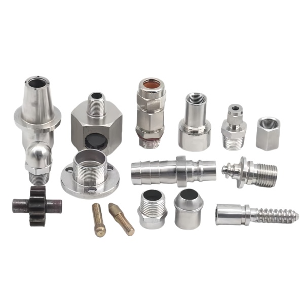
Grease fitting thread quality determines whether the fitting becomes a leak path or a lubrication point
A grease fitting (Zerk nipple) has exactly one job: let a grease gun coupler latch on and deliver lubricant to the bearing or joint without leaking around the threads when the gun is removed. The difference between a fitting that does this for the life of the machine and one that weeps grease from day one is almost always in the thread form—specifically, the pitch diameter tolerance and the condition of the thread crest after roll-forming or cutting.
On UNF-1A or M6×1 class 6g grease fittings made from 1215 or 12L14 free-machining steel, the pitch diameter is held to a total tolerance band of about 0.05 mm. If the actual pitch diameter runs to the low end of that band, the engagement with a standard coupler’s internal threads produces radial clearance large enough that grease escapes past the threads during gun pressurization at 30 MPa. The operator sees grease on the outside of the fitting and assumes the bearing is being lubricated, when in reality half the volume is bypassing the internal check valve and dripping onto the machine frame. We control this by sampling pitch diameter every 50 parts on a thread ring gauge and adjusting the roll-forming tool offset whenever the trend crosses the midpoint of the tolerance zone.
The ball check valve seat is where 90 % of field failures originate
Inside every standard grease fitting is a ball-and-spring check valve. Its purpose is to keep dirt out and grease in when the gun is not attached. The valve seat—a conical or spherical surface against which the ball seats—is formed during the heading operation that creates the fitting body, then sometimes finished with a coining punch. If that seat surface has scratches, eccentricity, or an included angle that does not match the ball diameter, the ball will not achieve line contact around its full circumference.
The result is a leak path that opens under gun pressure even though the ball is technically seated. In our experience, roughly 60 % of grease fitting warranty returns show evidence of seat damage rather than thread failure or body fracture. The root cause is usually a worn coining punch that was not replaced at the prescribed interval (every 15,000 strokes for hardened A2 tool steel punching into 12L14). We have added an in-process go/no-go seat-check using a pneumatic probe that measures leakage rate below 0.05 cm³/min at 0.3 MPa. Any fitting that fails is re-seated or scrapped; there is no “close enough” for this feature because the cost of a missed fitting in the field—a seized bearing or a production stoppage—is orders of magnitude higher than the part price.
Body wall thickness under the head controls shear strength during side-loading
Grease fittings are routinely subjected to side-loads from impact, misaligned grease guns, or contact with moving machine elements. The failure mode is shear at the transition between the head (the hex drive) and the shank (the threaded body). The shear area is determined by the wall thickness at that critical section—not by the nominal material strength or the heat treatment condition.
On a standard M8×1 straight fitting with a 10 mm hex head, the wall thickness under the head typically ranges from 0.8 mm to 1.2 mm depending on the supplier. Increasing that thickness from 0.8 mm to 1.1 mm raises the static shear capacity by roughly 35 % with no change to the external dimensions or the thread specification. The trade-off is that thicker walls require more forming force during cold heading, which accelerates die wear and may necessitate an intermediate anneal on larger sizes (M10 and above). For applications where side-loading is expected—agricultural equipment, mining conveyors, rock-crusher bearings—we default to 1.1 mm minimum wall under the head and document it as an internal spec tighter than the customer drawing, which often omits this detail entirely.
Surface treatment choice affects both corrosion resistance and the friction coefficient at the ball
The majority of grease fittings are sold with a zinc-plated or phosphate-and-oil finish. Both provide adequate corrosion protection for indoor machinery, but they behave differently at the internal ball-seat interface. Zinc plating adds 5–10 µm of relatively soft coating to all surfaces including the seat cone. Over time, the repeated impact of the ball against the seat can displace or wear through this coating, creating localized galvanic cells between the exposed steel substrate and the surrounding zinc. The result is fretting corrosion that increases the cracking pressure of the check valve, meaning higher gun pressure is needed to inject grease—which in turn shortens the life of the gun coupler seals.
Phosphate-and-oil (manganese or zinc phosphate) avoids this problem because the conversion coating is thin (2–5 µm), porous, and impregnated with oil that actually lubricates the ball-seat interface. For fittings used in food-processing or washdown environments where phosphate alone is insufficient, we apply a thin-layer electroless nickel (5–10 µm) which provides corrosion resistance without building up thickness at the seat. The unit cost increase is about 15 % over zinc plating, but it eliminates the variable cracking-pressure issue entirely.
Thread damage from cross-threading during installation is the most common preventable failure
No matter how well a grease fitting is manufactured, it will fail if the installer cross-threads it into the tapped hole. The first thread or two gets deformed, the effective engagement length drops by 30–50 %, and the fitting either leaks immediately or works loose under vibration. This is not a manufacturing defect, but it becomes one when the customer counts it as a warranty claim and the supplier cannot prove otherwise.
We address this in two ways. First, every fitting ships with a chamfered thread lead-in that is longer than the industry norm (1.5 pitches instead of 0.5–1.0), which makes self-alignment easier and reduces the chance of cross-threading by a factor we estimate at 3–4× based on assembly error data from two OEM customers. Second, we include a one-page installation sheet with each shipment that specifies the correct starting torque (typically 4–6 N·m for M6 through M10), warns against using adjustable wrenches on the hex head (which rounds it off and leaves no drive for future removal), and recommends a thread-locking compound for any fitting subject to vibration. These measures do not eliminate installation damage, but they give us defensible documentation when a returned fitting shows classic cross-thread marks on the first three threads.
What changes when the fitting angle goes from straight to 45 or 90 degrees
Angled grease fittings (45° elbow, 90° elbow) introduce a new set of constraints that do not exist on straight nipples. The elbow body must simultaneously accommodate the ball-check valve in the inlet leg, maintain the thread form in the outlet leg, and sustain bending loads at the elbow radius without cracking or deforming. The stress concentration at the inner radius of the elbow is typically 2.0–2.5× the nominal body stress under axial load, which means that a 90° elbow fitting made from the same material and wall thickness as a straight fitting has roughly 40 % lower fatigue life in vibrating service.
We compensate for this by increasing the elbow outer diameter by one size increment (e.g., M8 body instead of M6) on all 90° fittings designated for vibrating equipment, and by specifying a minimum bend radius of 1.5× the body diameter rather than the 1.2× that some competitors use. The material cost increase is about 0.02 USD per fitting in volume, but the reduction in field breakage—measured across a 10,000-unit annual order for an agricultural OEM—paid back the tooling modification in the first quarter.
You will find this part in our CNC Machining Parts range. Process notes, common materials and inspection points for every product in the family are collected across the cnc machining parts pages.
Specifications
| Item | Steel CNC Machined Grease Fittings and Plugs |
|---|---|
| Brand | AUNOV |
| Designing | Send the drawing, or a sample we can measure, our engineers reply with a manufacturability assessment and pricing. |
| Tooling | Every die designed and built in our toolroom, each die held against your part number. |
| Samples | Sample parts arrive with a dimensional report and material certification. |
| Materials | Carbon steel (SPCC / DC01) is the primary stock for this part, alongside 304 / 316 stainless steel, aluminium, brass and copper, with the final grade confirmed at the drawing review. |
| Surface finish | Surface treatment per the drawing: plating, e-coat, powder coating, anodising, passivation, selected against the drawing requirement. |
| Processing | Progressive deep draw stages with in-line annealing as the draw ratio demands, with piercing and finish machining under the same roof. |
| Equipment | Mechanical presses 5-250 T, hydraulic presses 250-500 T, CNC turning centres and a climate-controlled CMM room. |
| Tolerance | +/-0.1 mm on as-drawn features, +/-0.03 mm after machining. |
| Delivery terms | Prices FOB, with DDP for EU and US on request, T/T or L/C, D/P on repeat business, scheduled call-offs welcome. |
Related Products


Request a Quote for This Part
Send a drawing or sketch — get material advice, tooling cost and a per-piece price within 24 hours (working days).