
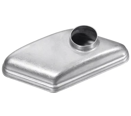
A rectangular cover with a round port serves two neighbours that disagree
A drawn rectangular cover with a round neck port is a one-piece sheet metal closure: its plan view is rectangular with radiused corners so it can close a matching aperture, while one of its faces carries a raised cylindrical neck so something round can be connected to it. Those two requirements come from different parts of an assembly — the rectangle is what the housing asks for, the round neck is what the hose, tube or fitting asks for — and the interesting engineering is that a single blank has to satisfy both at once.
The part is drawn rather than built up from several pieces for one reason above all: every seam is somewhere it can leak, distort or drift out of position. Keeping the flange, the body and the neck in one continuous piece of metal removes that joint, and it also removes the tolerance stack-up a welded-on spud would bring with it. What it costs is a more demanding draw, because non-round geometry does not let the metal behave predictably.
In practice the rectangle usually exists because the aperture it closes was cut for something else — an inspection opening, a manifold face, a rectangular port on a housing — and the neck exists because whatever connects to it, whether a hose, a tube or a threaded fitting, is round. Neither dimension is arbitrary, which is why the two cannot be traded against each other late in design: change the plan shape and you are changing what it bolts to, change the neck and you are changing what it connects to.
Why the rectangular plan is the harder half
In a round draw the metal flows toward the centre at the same rate all the way around, so the tooling can be designed around one repeatable condition. A rectangular plan has straight edges and corner radii doing two different things: along a straight run the metal draws inward with little restraint, while at a corner it has to turn and compress at the same time. Left to itself that difference shows up as waviness along the straight runs and local thinning where the corner radius has been fighting the draw.
It is controlled at the blank and the hold-down rather than at the finish. The developed shape is not the rectangle’s area rearranged; it is trimmed back where the flow is easy and left generous where a corner needs material to turn. Uneven blank holder pressure is the fastest way to lose this part, so the force is set deliberately and recorded rather than left to a press setter’s judgement.
The corner radius carries more weight than it looks like it should. Open it too far and the plan stops reading as a rectangle; close it tight and it becomes where the metal runs out of ductility first. In practice it is settled against the draw depth rather than chosen for appearance, because it is the one number linking how deep this cover can be formed to how square it can still look.
The neck has to be grown before it can be opened
A round neck port is not a hole. Before there can be a mouth there has to be a cylinder, and that cylinder has to be lifted out of the same sheet the flange came from. The sequence is therefore to raise a boss, draw it to the height the connection needs, and only then trim or roll the end. If the collar is rolled, there has to be enough wall left above the trim line to roll; if the mouth is to stay square, the trim has to land cleanly and the edge condition becomes part of the drawing.
That order is also why the neck tends to decide the number of stations. The height achievable in one stage is limited by how far the material will go without thinning through the wall, and a tall neck on a shallow body asks those two things to happen at different rates in the same operation.
How the mouth is finished also decides what happens next. A rolled or flared edge spreads a hose clamp’s load and takes the sharpness off the trim line, which matters when someone has to reach past it; a plain trimmed mouth is cheaper and takes up less height, which matters when something sits above. Both are achievable on the same drawn boss, but not from the same trimmed length, so the choice belongs on the drawing rather than being settled at the press.
Port position is a tooling decision, not a drawing afterthought
A port on the centreline behaves nothing like one set toward an end of the cover. Offset to one side, the metal that feeds the neck comes preferentially from the nearest edge, so the wall on that side thins and the opposite side carries material further than planned. Moving a port late in a project is therefore rarely the small drawing change it looks like; it moves where the blank has to be thicker, which means re-developing the blank and often re-cutting the die.
On the cover shown here the neck sits toward one end rather than in the middle of the panel, and that single choice governs the blank development. It is also why port position belongs on the drawing with its own tolerance, referenced to a datum the assembly actually uses rather than to the trimmed outline.
Referencing the port back to the trimmed outline is the error we see most often on drawings like this. The outline is the least controlled surface on the part, because it is the last thing that happened and it carries the accumulated variation of every earlier stage. Referencing to a datum that survives trimming keeps the port where the assembly expects it regardless of how the trim lands.
The flange is the sealing surface, and the cover shape fights it
Whatever the neck does in service, the flange is what has to seal. A non-round flange has corners to hold and straight runs to hold, and those two relax differently once the part leaves the die: the straight sections spring and the corners stay stiff, leaving a flange that is flat at the corners and lifted along the middle of each edge. A gasket does not bridge that, so flatness has to be stated as a requirement and won with a restrike rather than assumed.
Whether the flange face is left as drawn or finished depends on duty. Machining only the land the gasket sits on is usually the economical answer, because stating the whole flange to a machined class buys nothing at the sealing line.
Bolting is worth designing for at the same time. Holes pierced through a corner radius behave differently from holes pierced through a straight run, and they are generally better placed in the flat than across a radius, where the punch enters work-hardened material at an angle. Piercing after forming keeps them where the drawing put them, while piercing before hands that decision to the draw.
Stainless steel springback, and where annealing comes in
Austenitic grades work-harden as they draw and spring back more than carbon steel or aluminium. On this geometry that has consequences: the trim wants to move after forming, the neck wants to lean, and a second stage that would be routine in a softer material may need a relief anneal first. Whether it does is decided by the total reduction rather than by habit, so it is resolved at feasibility and quoted openly — the stage count is the tooling cost.
Passivation is part of finishing rather than an optional extra, because the trimmed mouth of the neck and the drawn corner radii are where a stainless steel part is most often judged afterwards.
Springback is designed around rather than removed. Rather than predicting exactly how far a feature will move, we hold what has to be right at the operation that creates it: the restrike sets the flange, the trim is taken from a datum rather than from an edge, and the neck is brought to size where the drawing needs it held. Capability is then checked on the first article before a run continues, which is where a borderline tolerance gets confirmed or reopened.
What belongs on the drawing
Three things decide how well this part goes. A datum scheme that refers both the flange and the neck back to one feature rather than to the trimmed outline; a stated relationship between the neck centre and that datum, since position governs the blank; and a flatness requirement on the sealing land that is separate from the size callout. Everything else can be worked out in review, but those three are expensive to discover once tooling exists.
Two questions are worth asking at enquiry because they change more than their apparent size: whether this part needs stainless steel at all for the duty it will see, and whether a drawn one-piece cover is really the right route for this geometry. Both are far cheaper to answer before tooling is cut than after the first part comes out of the press.
Getting the first one right matters because tooling is quoted once and held, and the sample you approve becomes the reference later batches are gauged against. Recorded settings against the part number are the difference between repeating a part and developing it again.
Sizing the draw for a part like this — reduction per station, ironing allowance, flange width — is covered step by step in our deep drawn covers guide.
Specifications
| Item | Drawn Rectangular Cover with Round Neck Port |
|---|---|
| Brand | AUNOV |
| Designing | Driven by your drawing or a physical sample – unusual walls, threads or tolerances are feasibility-checked first; the agreed version governs every later batch. |
| Tooling | Tooling is quoted once and held – reorders are priced on the part, not on the die. |
| Samples | The sample you approve becomes the gauge reference for production. |
| Materials | Stock covers carbon steel (SPCC / DC01), 304 / 316 stainless steel, aluminium and brass; mill certificates and heat numbers accompany the first article. |
| Surface finish | Finish per the drawing: plating, coating, anodising or passivation, plus masking and laser marking where needed. |
| Processing | Tube or sheet preform, hydroforming into the finished contour, trimming, then annealing and finishing. |
| Equipment | Press shop running 5-250 T mechanical and 250-500 T hydraulic presses, annealing ovens on site; first articles and batch samples are checked on the CMM. |
| Tolerance | +/-0.05 mm on flange and rim dimensions, wall controlled by the draw; capability is checked on the first article before the run continues. |
| Delivery terms | FOB, CIF or DDP per Incoterms 2020, T/T or L/C, with D/P accepted on repeat business; sea or air freight is quoted to your door. |
Frequently Asked Questions
Can the rectangular shape and the round neck be formed in one operation?
Almost never. The body wants to be drawn broadly across its whole plan area while the neck needs height developed in one local place, and those two ask for different reductions. They are normally sequenced, with the neck raised and grown while the surrounding form is still able to feed it.
Why does moving the port cost more than the distance suggests?
Because port position decides where the blank has to be thick. An offset port draws preferentially from the nearest edge, so moving it changes the developed blank rather than just relocating a feature, and that usually means new tooling rather than a new dimension.
Does the flange need machining, or is the drawn face enough?
It depends on what the flange has to do. If it seals, the sealing land is normally finished and the rest is left as drawn, since a machined class over the whole flange costs money without improving the joint. If it only locates, the drawn face is usually adequate once flatness is held.
Will this cover need an intermediate anneal?
That is decided by the total reduction, not by the material alone. Austenitic stainless steel work-hardens fast, so if the neck and the body together exceed what one sequence can take without thinning through the wall, a relief anneal is planned into the stage table and quoted as part of the tooling rather than added later.
Related Products



Request a Quote for This Part
Send a drawing or sketch — get material advice, tooling cost and a per-piece price within 24 hours (working days).