
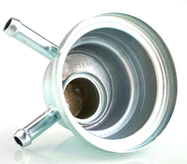
A three-port hydraulic chamber has three penetrations and one interior, and both are critical
A deep drawn and dip brazed aluminium hydraulic chamber with three ports is a small aluminium pressure chamber, and every part of that description is a design constraint. It carries fluid at pressure, it has three penetrations through its wall, and it is joined by a process that requires the parts to be assembled before they are joined. Those three facts together determine almost everything about it, and they determine it in a way that a general drawn housing is nowhere near.
We deep draw on maintained presses with blank size and lubrication logged per run, and first articles verify the whole flow before the run is released, on a press shop with 5-250 T mechanical and 250-500 T hydraulic presses with annealing ovens on site, CNC turning centres for secondary operations, and CMM inspection. Formed features to +/-0.05 mm with capability data on critical dimensions, and critical dimensions carry CMM data with the shipment. Standard stock is carbon steel in SPCC and DC01 grades, 304 and 316 stainless steel, aluminium and brass, with grade and temper confirmed in writing before tooling. Natural, plated or coated per the print, with the agreed finish logged and alternatives quoted alongside. This page is about the chamber as a pressure boundary, the three ports as penetrations, and the process’s structural limits.
It is a pressure boundary, and the wall is calculated
Hydraulic pressure is high – working pressures of several hundred bar are normal in hydraulics – and a thin drawn aluminium wall does not survive that without a design. The requirements:
- Wall thickness from a calculation, not a preference. For a cylindrical chamber the hoop stress governs and the wall requirement follows from the pressure, the material’s allowable stress, and the diameter. On a small chamber the required wall is thin, which is why a drawn chamber is a credible construction at all – the diameters are small enough that the pressures are manageable.
- The corners are where it fails. A drawn chamber has corners where the wall transitions from one face to another, and a corner is both a stress concentration and a place where the wall has thinned. Any chamber with sharp internal corners at a pressure-carrying region needs generous radii, and a corner with a tight radius on a pressure boundary is a design defect.
- The ends of a drawn chamber are the weak part. A drawn cup’s wall thins toward its depth, so the closed end is thinner than the side. On a pressure boundary the closed end is often the highest-stress region because it carries the full pressure across a smaller area. The minimum wall is at the punch nose in the base, and that is where the calculation has to be done.
- Test pressure versus working pressure. Hydraulic components are usually proof tested well above working pressure, often at a defined multiple. A chamber designed for 200 bar working is typically tested at 300, and the test pressure is a requirement on the drawing rather than a shop decision.
Three ports, three penetrations, three sets of requirements
Each port is a hole through the pressure boundary, and each one is a place where the design has to solve the same four problems differently depending on what the port does. The four problems are:
- How the penetration is made. A machined and tapped hole, a drawn boss with a threaded insert, a brazed-in fitting, or a welded fitting. On a dip-brazed chamber the fitting is very often brazed in as part of the assembly, which is elegant and strong, and which means the fitting is a component of the brazed assembly with its own alloy compatibility requirements.
- Reinforcement of the wall around it. A hole removes the material that was carrying the hoop stress around it, so a ported wall is weaker than a plain wall. A port in a cylindrical wall needs a boss, a pad, or a thicker local section, and this is a stress calculation rather than a detail. Three ports in close proximity interact – the material between two ports is carrying less than it did before either was cut.
- Sealing. On a hydraulic port this is a metal-to-metal seal – a tapered seat, a cone, a bonded seal, or an O-ring in a machined groove. A drawn wall’s surface cannot be a sealing surface, so the seat has to be machined, and the seat’s geometry – its angle, its diameter, its finish – is a functional specification with a tight tolerance.
- Alignment and angle. Where the ports have to connect to a customer’s valve block or manifold, their positions and angles are functional tolerances. Two ports a degree apart in angle will not seal, and a chamber with three ports has more alignment requirements than one with a single port.
Port types, and why the distinction matters
| Threaded port | The simplest and the most common. Requires enough thread engagement to carry pressure, which in a drawn boss means a long boss. Where the port is brazed in as a separate fitting, the fitting’s thread is machined and its reliability is entirely its own. |
|---|---|
| Metric fine or tapered seat | A cone-seat port gives a good seal with a controlled tightening torque and is very common in hydraulics for exactly that reason. It requires a defined seat angle and a controlled surface finish, both of which are machined features. |
| Face-seal port | Where the port mates to a flat face with an O-ring or a bonded seal. This is the tightest option and the most sensitive to surface finish and flatness, and it is the one that most often needs a machined face at +/-0.03 mm. |
| Bonded seal port | A seal bonded into the port’s face. Convenient and leak-tight, and it is destroyed by the brazing cycle, so it has to be fitted after brazing – which is an assembly-sequence requirement that has to appear on the drawing. |
What dip brazing means for a pressure chamber
The process adds five specific requirements to a part that is already a pressure boundary:
- Flange overlap is a structural parameter. A chamber’s wall is joined to its end face by a lap joint, and the overlap has to be long enough that the joint carries the pressure. A thin-wall chamber’s joint is often a continuous return flange around the perimeter, and its width is a design number.
- Vent and drain holes are mandatory. Trapped air prevents the filler from entering the joint and trapped flux stays inside the chamber forever – and trapped flux inside a hydraulic chamber is a corrosion and a contamination problem. The vent and drain positions are design features and are rarely on the drawing.
- The joint’s flatness is the chamber’s alignment. If the port’s end face and the chamber’s mating flange are not parallel, the port will not sit square and the seal will not be uniform.
- Nothing that melts goes in before brazing. Seals, plastic, elastomer, plated surfaces, and bearings all have to be fitted afterwards, and on a three-port chamber that means the assembly sequence has to be designed.
- The pressure test is after brazing, always. A chamber that has not been pressure tested after brazing has not been tested, because the brazing is what created the joints. This is the functional acceptance test and it belongs on the drawing as a requirement with a method.
Material, and the seal question
Standard stock is carbon steel in SPCC and DC01 grades, 304 and 316 stainless steel, aluminium and brass, with grade and temper confirmed in writing before tooling. On a dip-brazed hydraulic chamber, the practical choices are narrow and the reason is the brazing:
- Aluminium, brazed. The standard answer, and the reason is thermal: aluminium moves very little when the chamber’s temperature changes, so the chamber’s dimensions are stable and the seals stay tight. A steel chamber would expand several times more over the same temperature range, and a hydraulics customer working across a wide temperature range would see the seals leak at the cold end. This is a real design argument and it is worth putting on the drawing as a reason.
- Aluminium, welded or machined. The right answer where the volume is low or where the geometry cannot be brazeable. A welded aluminium chamber is leak-tight, cheaper at low volume, and has no filler in it. It distorts more than a brazed one, and that is the trade.
- Stainless Steel is not brazable in the aluminium sense and would need a completely different joining method. It appears on this drawing as a general stock note rather than as a realistic option for this part.
- Brass is brazeable with a different filler system, and it is used where a specific corrosion or conductivity requirement applies. It is a legitimate option and it changes the filler choice.
A hydraulic chamber wants hard anodising, not a decorative coat
Natural, plated or coated per the print, with the agreed finish logged and alternatives quoted alongside. On a hydraulic chamber:
- Anodising is the natural finish – hard, cleanable, corrosion-resistant, and dimensionally stable. On a part with ports, the port surfaces are usually masked, because a coating on a cone seat or a thread will change its function.
- Mask every port’s functional surface, every thread, and every machined seat. This is a per-part operation on a three-port chamber and it belongs in the cost.
- Where the chamber is a sub-assembly in a larger hydraulic system, the exterior finish is often not important at all, and the requirement is simply that the surfaces are clean and free of flux residue. Flux residue left on a chamber and then assembled into a system will contaminate the system.
A welded chamber, or a brazed one
Eight things, and the first four are what make this a hydraulic component rather than a drawn box:
- Working pressure, test pressure, and the medium, plus the temperature range. These set the wall, the material, and the seal type, and they are the first thing missing from a drawing that calls itself a hydraulic chamber.
- Each port’s type and thread or seat specification, with its sealing method.
- Each port’s position and angle, as true position and angle against a named datum, and what the chamber mates to.
- Wall thickness, with its minimum location, and the port bosses’ dimensions.
- Each port seat’s or thread’s tolerance, at the tight band, plus the seat angle and surface finish where a cone seat is used.
- Every brazed joint’s overlap and gap, plus the vent and drain hole positions.
- The pressure test requirement – test pressure, hold time, media, and that it is after brazing.
- Which features are fitted after brazing, and which surfaces are masked from the finish.
Does this chamber need to be dip brazed?
Does this chamber need to be dip brazed, or would a welded aluminium chamber do the job? For a hydraulic chamber, dip brazing’s real advantage is that it is very repeatable and it does not distort the part – which matters enormously when the ports have to stay in alignment. A welded chamber is cheaper and can be leak-tight but will distort, and three distorted ports are three ports that might not line up. The trade is cost against dimensional stability, and it is worth establishing early which of those matters more for this assembly, because the answer determines the process, the tooling, and the tolerance scheme.
Not sure whether to draw, machine or weld this geometry? The guide to deep drawn covers compares the three routes and shows where each one wins; the full Precision Deep Drawn Parts range is linked from the overview page.
Specifications
| Item | Deep Drawn and Dip Brazed Aluminum Hydraulic Chamber |
|---|---|
| Brand | AUNOV |
| Designing | The quotation follows your print, not a catalogue – unusual walls, threads or tolerances are checked for feasibility first. |
| Tooling | Progressive and drawing dies are designed and built in house, so tooling lead time stays under our control, and first-article timing is measured from the tooling start date. |
| Samples | Prototype and pre-production samples are provided against the drawing, so the sample is retained as the master, and production starts only after your written sign-off. |
| Materials | Standard stock: carbon steel (SPCC / DC01), 304 / 316 stainless steel, aluminium, brass; grade and temper are confirmed in writing before tooling. |
| Surface finish | Natural, plated or coated – the print decides, and the agreed finish is logged; alternatives quoted with the quotation, samples approved in writing. |
| Processing | Deep drawing on maintained presses, blank size and lubrication logged per run; first articles verify the whole flow before the run is released. |
| Equipment | Press shop running 5-250 T mechanical and 250-500 T hydraulic presses, annealing ovens on site, with CNC turning centres for secondary operations and CMM inspection. |
| Tolerance | +/-0.05 mm on formed features, with capability data on critical dimensions; critical dimensions carry CMM data with the shipment. |
| Delivery terms | Delivery quoted per Incoterms 2020 – FOB, CIF or DDP – by sea or air, to your address. |
Frequently Asked Questions
Why is a hydraulic chamber dip brazed rather than welded?
Dip brazing joins the three ports and baffles to the drawn shell in a single controlled bath, giving a uniform fillet and a clean interior that a manual weld bead cannot match. For a pressure boundary that also has to stay clean inside, brazing avoids the porosity and heat distortion that welding a thin drawn wall tends to introduce.
What pressure can a deep drawn aluminum hydraulic chamber contain?
The wall is calculated as a pressure boundary, not just a shape, and the limiting case is the thinnest section after drawing and brazing. Working pressure is set by that calculated wall with a margin, so the drawing has to state the pressure and the fluid before the shell thickness is fixed.
Which aluminum alloy is used for the brazed chamber?
A weldable 5xxx or 6xxx grade is specified so the braze takes cleanly and the part resists corrosion in its service fluid. The alloy is chosen for brazeability and environment together, and the anodising that follows is selected for a pressure part rather than appearance.
How are the three ports located and sealed on the chamber?
Each port is a formed or machined feature located off the drawn shell datum, so all three stay related to the same origin. Sealing is by face or thread at the port, and the joint is verified because a chamber like this fails at a penetration long before the wall does.
Related Products


Request a Quote for This Part
Send a drawing or sketch — get material advice, tooling cost and a per-piece price within 24 hours (working days).