
Temperature is the most casually specified quantity in manufacturing. It is also the one most frequently wrong by a margin that ruins the work. The reason is that temperature at a point is not a property of the material there — it is a property of a measurement, and the measurement is only as good as the sensor, the installation, the electrical path and the moment in time it was taken.
Most temperature errors are not sensor errors. A thermistor of the correct type, of the correct resistance, correctly calibrated, installed badly will still read wrong. The installation contributes more error than the sensor in almost every industrial application.
Thermal error budget: where the degrees actually come from
For a contact temperature measurement in a process or a duct, the error contributors in rough order of magnitude are:
- Thermal contact error. The sensor surface and the measured surface do not have the same temperature. This is usually the largest single contributor and it is entirely a function of how the sensor is mounted.
- Spatial error. The sensor is at one point; the “temperature” the process means is often an average. In a hot work, a mixing vessel, or a duct with stratification, this can exceed every other error combined.
- Response error. The reading is a weighted average over the sensor’s thermal time constant. In a changing process this is not a small error.
- Self-heating. The measurement current heats the sensor. At high resistance this is small; at low resistance it is not.
- Lead and contact resistance. Usually a percentage effect, but occasionally the whole problem when a joint degrades.
- Sensor tolerance and calibration drift. Frequently quoted as the dominant term in datasheets and, in real installations, one of the smaller ones.
The ordering above is the useful part. It says that buying a more accurate sensor is the wrong lever. Fixing the mounting is the right one.
Contact is a thermal joint and it behaves like one
When a probe tip touches a surface, there is a real thermal resistance at that interface — a contact resistance that depends on surface roughness, contact area, contact pressure, and whether there is a filler between the two.
A dry metal-to-metal contact has excellent conductivity but an unpredictable resistance, because the resistance is set by the condition of the surfaces at the moment they touch. A paste-filled contact is predictable and slightly worse in bulk, and it is the arrangement used for serious measurement. A clamp without filler is the worst option: it looks like good contact and behaves like a poor one.
The consequences for the sensor package are direct. A probe intended to be clamped must be designed for the contact resistance that clamp will produce, which typically means:
- A tip flattened with a defined contact area, so the resistance is a defined number rather than a random one.
- A tip material that will not be scratched by the mating surface, and will not transfer material onto it.
- A flatness and parallelism band, because a rocked contact touches on one edge and the reading moves when the clamp pressure changes.
- An acceptance test on the actual assembly, not just on the probe.
All of this belongs in the specification of the probe, not in the assembly instructions, because the probe is what determines whether the design can work.
Insertion depth decides whether you are measuring the process
Any probe inserted into a fluid is inside a thermal boundary layer — a stagnant layer of fluid against the metal, warmed by the metal rather than by the bulk flow. The probe tip senses the boundary layer, not the process.
The boundary layer is thin. Reading the process requires the sensor to be far enough inside that the fluid around the tip has been replaced by fluid from the bulk, which in practice means an insertion depth of at least ten diameters — more if the fluid is viscous, more if the flow is laminar, more if the sensor is close to a wall or a bend.
This produces an uncomfortable but genuine trade-off:
- Insert deeply and the reading represents the process, but the sensor is exposed to the fluid, may corrode, and may obstruct the flow or foul the vessel.
- Insert shallowly and the sensor stays clean and protected, but the reading is dominated by the wall and by the mounting it sits in.
Where the process fluid cannot be tolerated inside the sensor, the answer is a thermowell — and then the error budget changes completely. The well wall adds its own thermal resistance and, more importantly, adds a temperature gradient. A thermowell reading is the process temperature plus an error that depends on the convection coefficient inside the well and on the thermal conductivity of the well material, and the conduction error in a stainless steel well is small while the convection error is not.
For gas streams this matters more than for liquids. Gas has a low heat transfer coefficient, so the boundary layer on a probe in air is thick and the insertion depth requirement is correspondingly large. Air temperature measurement is where badly installed probes look worst.
Self-heating and the measurement current
A thermistor needs current to be measured. That current dissipates as heat in the sensor, and the sensor is a very good conductor of that heat to the process. The result is a reading that is systematically above the true temperature.
The magnitude scales with the square of the current and inversely with the element’s dissipation constant, so it is a design trade rather than an inherent property. Practical consequences:
- Higher resistance elements self-heat less for the same current. A 100kΩ element can often be measured continuously; a 10kΩ element in the same probe may need duty-cycled excitation.
- Long measurement intervals let the sensor cool back to the process temperature between readings, at the cost of response.
- In low-accuracy applications, a continuous low current is often entirely adequate and removes the need for any of this.
Note the interaction with the time constant. A probe with a fast response will also self-heat more at a given current, because it cannot shed the heat as quickly. Fast response and low self-heating pull in opposite directions, and the resolution between them is a genuine specification decision.
The electrical side, and why three wires exist
A two-wire thermistor has its lead resistance in series with the element, and that resistance sits inside the measurement. Whether it matters depends entirely on the ratio.
For a 10kΩ element with 0.1Ω of lead, the error is one hundredth of a percent and no one will ever notice. For a 100Ω element at the end of a long cable, the error can be several percent and will be attributed to the sensor.
- Two-wire is correct when the element resistance is high compared to the total lead resistance. It is the standard for 10kΩ and above at short distances.
- Three-wire adds a reference conductor to one side of the element so the lead resistance can be measured and subtracted. Correct where the element is lower-resistance or the run is longer.
- Four-wire passes current and measures voltage on separate conductors, removing lead resistance entirely. The right answer for reference measurements and for anything where the calibration is the point.
Beyond the resistance itself, three points cause more trouble than the theory suggests. Thermoelectric voltages at dissimilar junctions create a millivolt-level offset that appears as a temperature error. A shield grounded at one end only avoids a ground loop. And a lead whose insulation degrades with temperature creates a leakage path that is temperature-dependent — so the error is worst exactly where accuracy is most needed.
Calibration is a statement about conditions, not about a part
A calibration certificate is valid for a sensor used as it was calibrated: in the same configuration, at the same immersion depth, with the same electrical connection, at a rate of change comparable to what it will see in service.
- Immersion depth is part of the calibration. A sensor calibrated at 100mm and used at 30mm is not calibrated.
- The surface condition is part of it. Calibrated on clean machined metal, used on a scaled or oxidised surface, reads differently.
- The electrical connection is part of it, because a two-wire calibration does not remove the three-wire correction.
- The response is part of it, for anything changing quickly.
The practical discipline that follows is unglamorous and effective: specify the sensor together with its mounting, specify the mounting’s thermal treatment, and calibrate the assembly. A calibration certificate for a loose probe is a statement about the probe and says nothing about the installation, which is where the error was.
Questions worth asking before ordering sensors
- What is the accuracy requirement stated as total error at a specified temperature, rather than as element tolerance at 25 degrees?
- What is the required immersion or contact depth, and is it achievable in the actual vessel or duct geometry?
- Is the probe thermally coupled to the process, or is it measuring through a thermowell — and if a well, is its influence in the error budget?
- Is the mounting material specified, and is the contact filler defined?
- For a low-resistance element over a long run, is the connection three-wire or four-wire, and does the calibration account for it?
- What is the excitation, and what self-heating error does it produce at the top of the temperature range?
- Is the calibration performed on the assembly in its installed configuration?
The last question is the one that changes results. Most calibration disputes turn out to be a disagreement about the installation, discovered after the sensor has already been specified and purchased. Settling it on the drawing costs nothing.
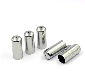
Deep Drawn Tubes & Sleeves is the parent range for parts like this one; the overview page gathers the tooling logic, finishing options and tolerance notes that apply across the family.
Specifications
| Item | Stainless Steel Small Closed Tubes, Five-Piece |
|---|---|
| Brand | AUNOV |
| Designing | Quotation follows the print, not a catalogue – a manufacturability review comes back with the quotation; the same drawing is used for every repeat order. |
| Tooling | Dies, fixtures and gauges are made in our own toolroom, so a die can be re-cut against the approved drawing, and ownership is confirmed on the quotation. |
| Samples | Pre-production samples come with a full inspection report, so any deviation is corrected at sample stage, and later batches are gauged back to the signed sample. |
| Materials | Carbon steel, 304 / 316 stainless steel, aluminium and brass are all held in stock; the final grade is fixed with the drawing review. |
| Surface finish | Finish per the drawing: plating, coating, anodising or passivation, plus masking and laser marking where needed. |
| Processing | Drawn-tube process with in-line annealing and finish turning; batch records are filed so a repeat order starts from approved data. |
| Equipment | Drawn-tube benches, in-line annealing and CNC turning, backed by CNC turning centres and a climate-controlled inspection room. |
| Tolerance | +/-0.02 mm on fitted diameters, +/-0.1 mm on formed ends; capability is checked on the first article before the run continues. |
| Delivery terms | CIF or DDP, with FOB available, T/T with deposit and L/C for larger runs; price breaks tie to annual volume. |
Related Products



Request a Quote for This Part
Send a drawing or sketch — get material advice, tooling cost and a per-piece price within 24 hours (working days).