
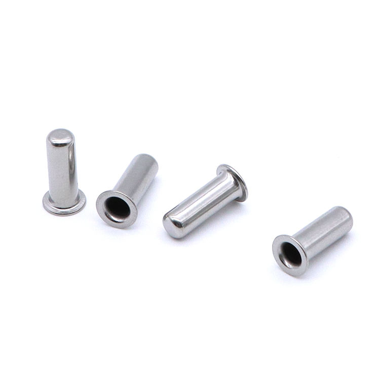
The Stainless Steel Precision Flanged Tube Bushing is a drawn tube with a formed flange at one end – a shoulder that locates the part in a housing and often carries axial load. This page covers flange forming and the cracking risk at the curl, flange squareness and the press-fit it governs, wall selection under side load, and the installation problems solved on the drawing rather than at the press.
Forming the flange: curl height, crack start and tool radii
A flange on a drawn tube is formed by flaring or curling the end outward – material bent out of plane at the tube mouth – and the process limit is written in the metal’s stretch capacity. The flange lip, as it turns outward, elongates along its outer edge: the outer fibers of the curl stretch by an amount that grows with flange diameter, and 300-series stainless steel tolerates roughly 15 to 20 percent elongation before the lip tears. A flange that needs more stretch than the metal has is not a tooling problem; it is a print that has to change – either by adding an anneal before flanging, by drawing the preform with a partial flare already started, or by rethinking the flange height-to-diameter ratio. We run this arithmetic at quotation, before tooling is cut, because discovering it on the first samples costs a tooling iteration.
The mechanics that produce good flanges are specific. The flanging punch must have a lead radius – a sharp-edged punch is a crack initiator, and the crack always starts at the same clock position, which is the tool telling you where its finish is worst. The flanging anvil supports the tube wall immediately below the bend zone, because an unsupported wall buckles inward as the curl forms. And the operation needs the end annealed if the part has been through sizing passes: a work-hardened tube end flanges to the sound of a click and the sight of a split lip. Our default routing for flanged bushings anneals or stress-relieves the tube end before the flanging station, and the routing sheet names that step explicitly so it does not fall out under schedule pressure.
Flange thickness at the lip is the named dimension most often forgotten. The curl thins as it forms – typically 8 to 15 percent depending on geometry – so the wall at the flange lip is not the wall on the body. Where the flange shoulders against a housing or carries clamp load, lip thickness belongs on the print and in the inspection plan, measured at the lip on the sectioned first article and gauged by lip-height-plus-body-wall arithmetic in production.
Flange squareness and the press-fit behavior it controls
The flange has two geometric jobs: it stops the bushing at a defined depth, and it squares the bushing in the housing bore. The second job is done by the flange’s underside face, and its squareness to the tube OD is what makes an installed bushing run true. A flange 0.5 degrees out of square on a 10 mm diameter body tilts the installed bushing by that angle – and if the bushing carries a shaft, the shaft now runs in a tilted bore, with edge loading on the bearing surfaces and everything that follows from it.
Flange squareness is a tooling-alignment outcome, not a material outcome: the flanging station’s punch, anvil and part clamp must be coaxial, and the squareness is verified per setup on the first parts with the flange seated on a surface plate against a height indicator reading the tube axis. We hold flange squareness to 0.2 degrees as our standard capability and quote tighter with a post-form sizing station where the design needs it – a sizing pass that clamps flange underside and body simultaneously, squeezing the squareness into the part rather than merely checking it.
The press-fit dimension interacts with all of this. The body OD press-fit band governs retention force in the housing; the flange squareness governs whether that retention is even around the circumference. An out-of-square flange seated hard against a housing face puts the body in bending during installation, which on a thin-wall bushing can bell the bore at the open end – the exact zone the shaft has to enter. The drawing-level fix is to make the press-fit band and the flange squareness a stated pair, and our inspection plan reports them as a pair, because a bushing that passes each check separately can still fail as an assembly.
Wall selection when the bushing carries side load
A flanged tube bushing is often more than a locator – it is the bearing surface for a pin, shaft or cable. Then the wall stops being a forming detail and becomes structure, and the design conversation is about deflection under load at the open end, where the bushing is least supported. For a cantilevered bore in a housing, the useful stiffness scales with wall thickness cubed at the mouth: a wall going from 0.5 to 0.8 mm roughly triples mouth stiffness, which is often the difference between a bushing that holds its bore under side load and one that bells outward and lets the shaft wander.
We work this with customers as a wall-versus-process negotiation, because wall affects manufacturability in both directions:
- Thicker walls draw well but flange harder – the curl needs more force, tooling pressures rise, and the anneal before flanging becomes mandatory rather than advisable.
- Thinner walls flange easily but risk buckling at the flanging anvil if support is imperfect, and they give up the structural duty quietly – no failure at our dock, a complaint at yours.
- The honest escape, where side load is serious, is a stepped wall: heavier wall at the flanged/mouth end, drawn down along the body where structure matters less. Stepped walls are a drawing-sequence decision made at blank stage, and quoting it early is dramatically cheaper than trying to buy it back later.
On material: 304 is the default and forms well; 316 earns its premium only under chloride exposure. What does not change with grade is the structural answer – stainless steel’s modulus is essentially identical across the 300 family, so paying for 316 buys corrosion behavior, not stiffness.
Installing without galling: surfaces, edges and the first insertion
Stainless Steel against steel or stainless steel, under press-fit pressure, is the classic galling pair: clean, smooth, similar metals that seize on first contact and then tear each other’s surfaces. A flanged bushing installation concentrates all the risk at one moment – the press-in stroke – and the countermeasures live on the drawing:
- Lead-in geometry on the bushing body – a short chamfer or radiused lead at the insertion end so contact begins progressive, not square. We default to a 0.3 to 0.5 mm chamfer at 30 degrees on press-fit bodies unless the print says otherwise.
- Surface texture on the fit diameter – counter-intuitively, a very smooth, glossy OD presses worse than a controlled matte finish, because a surface with no texture has nowhere to carry assembly lubricant. We specify and hold the fit-diameter finish to a defined Ra band rather than chasing maximum polish.
- Edge break at the flange underside – the flange’s inner corner where it meets the body can carry a burr from forming; that burr is the first thing to touch the housing face under press load, and it digs in and seeds galling at full insertion force.
- Material pairing guidance – where the housing is also stainless steel, we recommend a thin dry-film lubricant or a phosphate-free conversion option stated in the assembly instructions, and we raise this in the manufacturability review instead of assuming the installer will guess.
The verification of installability is a first-article event we strongly recommend: trial-press a sample into a fixture representing the housing bore, measure the retention force achieved, and archive the force-displacement curve as the installation record. It costs one fixture and an instrumented press, and it converts “should press fine” into a number the next lot can be compared against.
How we verify flange geometry and fit on every bushing lot
Verification on flanged bushings runs against the signed first article, per lot, with these named checks:
- Flange diameter and height – measured on the sample plan in our climate-controlled measuring room, with lip thickness confirmed on the sectioned first article and tracked by height arithmetic in production.
- Flange squareness to body axis – plate-and-indicator method on setup parts and lot samples, reported in degrees against the stated pair with the body fit band.
- Body fit diameter – two-axis measurement at defined stations, plus ovality reported, because a bushing that measures right on averages can still bell under press.
- Flange integrity – 10x visual for lip cracks at every flange on the first article and by sample plan in production; any crack is a reject-and-investigate event, never a use-as-is call.
- Edges and finish – chamfer presence at the insertion end, edge break at the flange underside, fit-diameter Ra against the specified band on the first article and by comparator in production.
- Installation record – where a trial-press fixture is agreed, the force-displacement curve from the first article retained on file with the bushing part number, so every reorder is compared to the proven installation, not just the proven geometry.
Send the housing bore dimensions, the press method and the load the bushing actually sees, and the review prices wall, flange ratios, edge geometry and the verification plan as deliberate engineering decisions.
Deep Drawn Tubes & Sleeves is the parent range for parts like this one; the overview page gathers the tooling logic, finishing options and tolerance notes that apply across the family.
Specifications
| Item | Stainless Steel Precision Flanged Tube Bushings |
|---|---|
| Brand | AUNOV |
| Designing | A drawing file or a physical sample starts the review, a manufacturability review comes back with the quotation. |
| Tooling | Our own toolroom designs and builds every die, stored under your part number. |
| Samples | The first-article set ships with a dimensional report plus material certs. |
| Materials | Stock for this part leads with 304 / 316 stainless steel, alongside carbon steel (SPCC / DC01), aluminium, brass and copper, and the grade is fixed at the drawing review. |
| Surface finish | Plating, e-coat, powder coating, anodising or passivation as the drawing calls out, selected against the drawing requirement. |
| Processing | Deep drawing in stages, in-line annealing where needed, pierced and machined on the same floor. |
| Equipment | Our press floor runs 5-250 T mechanical and 250-500 T hydraulic presses, CNC turning and milling cells, a climate-controlled CMM room. |
| Tolerance | Tolerances to +/-0.1 mm as drawn, +/-0.03 mm after machining. |
| Delivery terms | Standard terms FOB, DDP offered to EU and US, T/T or L/C, D/P on repeat business, call-off schedules supported. |
Related Products


Request a Quote for This Part
Send a drawing or sketch — get material advice, tooling cost and a per-piece price within 24 hours (working days).