
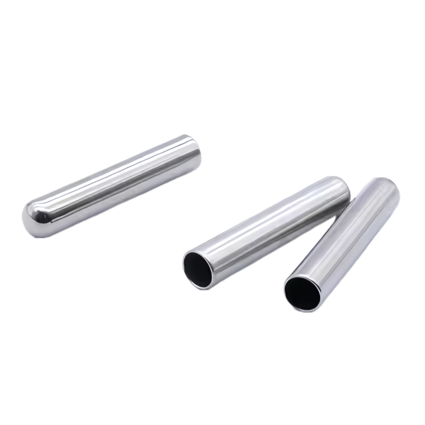
The Chrome Plated Steel Deep Drawn Tube Bushings is a load-carrying member, not just an envelope: a drawn shell whose machined and plated bore becomes the bearing surface for a shaft, a pivot or a roller. That single fact reorders the whole process plan – the drawing buys the wall, the turning buys the bore, and the chrome buys the running life. This page explains how the three stack into one part and what each batch is held to.
What changes the moment a tube becomes a bushing
The difference between a sleeve and a bushing is written in the loads: a sleeve locates, a bushing carries. A bushing’s bore sees radial load, side thrust and – in oscillating duty – edge pressure concentrated at the mouth of the bore, where the shaft’s deflection turns line contact into point contact. We manufacture to the duty, and the first question in the drawing review is always what runs inside the bore, because the answer decides the chrome strategy, the bore length-to-diameter ratio and whether the wall gauge drawn upstream is thick enough to survive press-fitting without bell-mouthing.
- A drawn bushing keeps the seamless wall that makes press-fit retention predictable – no weld seam acting as a local stiffener that distorts the bore roundness under installation force.
- Depth beyond roughly twice the diameter means staged drawing with anneals between passes; the stage plan is quoted openly because it sets both tooling cost and the wall uniformity the bore machining depends on.
- The wall is drawn deliberately over-thick at the bore region where load is highest – a free stiffening decision available only if the drawing review happens before the dies are cut.
One-setup boring: holding the bore true to the drawn wall
The bushing bore is machined after drawing on our CNC turning centres, and the process goal is a single setup that finishes bore, face and chamfer against one clamped axis. Every additional setup adds a concentricity stack between the bore and the OD the customer presses on – and a bore that runs true to itself but not to the press-fit OD translates directly into shaft misalignment in the housing.
- The as-drawn bore comes in around ±0.1 mm; the finished bearing bore is held to ±0.03 mm, so the boring plan removes a planned 0.15-0.25 mm per side of drawn stock allowance, enough to clean stage-to-stage variation without sacrificing wall.
- We clamp on the drawn OD and finish the bore against it, so concentricity of bore-to-OD is the measured result of one setup, not the sum of two tolerances – the number we report on the first article is the number the assembly gets.
- Where the print allows, the OD is also turned in the same setup, which closes the concentricity stack even further; where the drawn OD must stay as-drawn for cost, the review flags the residual concentricity budget so the customer signs it knowingly.
Bore finish is a functional call on a bushing: too rough and the chrome fills the peaks and sheds; too smooth and the bore cannot hold oil. We target the boring feed to leave a surface that plating completes rather than has to hide – typically finishing in the 0.8-1.6 µm Ra range before plating.
Chrome strategy for bores that see side load
Bearing chrome is not decorative chrome: the deposit on a bushing bore is a wear surface, and its thickness map is engineered against where the load sits. Uniform nominal thickness is the naive target; the useful target is minimum thickness at the loaded zone, which is mid-bore for a simply supported shaft and skewed toward one mouth for an overhung load or a belt-tensioned pulley.
- We hold typical bearing deposits in the 5-20 µm class per the drawing call-out, and we verify thickness at mid-bore, not at the convenient mouth – the difference between those two readings is exactly the difference between a bushing that wears in and one that wears out.
- Internal anodes bring current into bores deeper than about twice their diameter; a bushing too deep for throwing power gets its bore ground or turned after plating, converting the process to diameter-controlled finishing at the cost of one operation – we quote both routes when geometry qualifies.
- Bake-out at around 200 °C after plating is standard on our carbon-steel bushings to manage hydrogen uptake from the plating line; the cycle is recorded with the batch.
- Micro-cracked chrome distributes lubricant better than a dead-smooth deposit, and where the duty is boundary lubrication we say so in the review rather than chasing an unnecessary polish.
Press-fit arithmetic: retention force versus bore distortion
Most bushings of this family are pressed into a housing, and the press fit is a spring: the interference creates radial pressure, the pressure creates retention, and the same pressure shrinks the bore. A bushing pressed at 0.05 mm interference on a 1 mm wall will lose a meaningful share of that interference from its bore diameter – dimensionally invisible on the bushing print, decisive in the assembly. We do this arithmetic in the drawing review, and it is the reason we ask for the housing material and bore tolerance along with the bushing print.
- Where the assembly cannot tolerate bore closure, the bushing is supplied for retention by an adhesive or a keying feature instead of pure interference – a line on the drawing that removes a whole failure family.
- Wall gauge is drawn with press-fit distortion in mind: a thin wall that presses in happily will bell-mouth under load, and bell-mouthing concentrates every edge load the chrome was specified to survive.
- Where the customer assembles with a heated housing or cooled bushing, the retention arithmetic changes – thermal fits tolerate less interference than cold presses and the drawing review prices the difference honestly.
Deburring the mouths without bell-mouthing the bore
The bushing mouths deserve their own paragraph because they are where finishing sins collect. A chamfer machined with a worn insert rolls a burr into the bore; an aggressive hand-deburr fixes the burr and rounds the mouth into a bell; and either defect puts a hard edge into the shaft’s path or takes the bearing land away from the zone where edge load lives. The mouth is not an afterthought – it is the transition between the assembly’s tolerance stack and the bearing’s working length.
- Mouths are chamfered in the same CNC setup as the bore, so chamfer size, bore diameter and concentricity all inherit the one clamped axis and the first-article report says so.
- Edge condition is checked under magnification at first article and gauged per lot thereafter; burr height limits are written into the inspection plan, not left to the operator’s conscience.
- Plating rack contact points are kept off the functional lands by the racking plan – two tiny rack marks inside a bearing bore are two failures waiting for the first load cycle.
How we verify a bushing batch before it enters your housing
The acceptance sequence is fixed per part number; sampling intensity scales with volume.
- CMM first article: bore diameter at named sections including both mouths, OD at the press-fit zone, bore-to-OD concentricity, and overall length – all against the print in the climate-controlled room.
- Deposit verification: chrome thickness at mid-bore and at the loaded zone per the drawing’s minimum call-out, plus adhesion evidence from the qualification batch and bake-out records.
- Form and finish: bore roundness and cylindricity, bore surface texture in the as-plated or as-finished condition, and wall thickness at the thinnest drawn section.
- Mouth condition: chamfer dimensions, burr height against the written limit, and cleanliness of the packed parts.
- Traceability: mill certificate per heat, plating and bake records, and the signed first article that every production batch is gauged back to.
Deep Drawn Tubes & Sleeves is the parent range for parts like this one; the overview page gathers the tooling logic, finishing options and tolerance notes that apply across the family.
Specifications
| Item | Chrome Plated Steel Deep Drawn Tube Bushings |
|---|---|
| Brand | AUNOV |
| Designing | Send the drawing, or a bushing sample we can measure, the quotation comes back with a manufacturability review attached. |
| Tooling | Our own toolroom designs and builds every die, held under your part number. |
| Samples | Pre-production samples ship with a full dimensional report and mill certificate. |
| Materials | Stock for this part leads with carbon steel (SPCC / DC01), alongside 304 / 316 stainless steel, aluminium, brass and copper, and the grade is fixed at the drawing review. |
| Surface finish | Zinc, nickel or chrome plating, e-coat, powder coat, anodising or passivation, fixed at the drawing review. |
| Processing | Staged deep drawing with in-line annealing where needed, then pierced and machined in house. |
| Equipment | Mechanical presses 5-250 T and hydraulic presses 250-500 T, CNC turning and milling cells, a climate-controlled CMM room. |
| Tolerance | +/-0.1 mm on as-drawn surfaces and +/-0.03 mm on machined surfaces. |
| Delivery terms | Standard terms FOB, DDP offered to EU and US, T/T and L/C; D/P on repeat accounts, call-off schedules and blanket orders supported. |
Related Products

Request a Quote for This Part
Send a drawing or sketch — get material advice, tooling cost and a per-piece price within 24 hours (working days).