
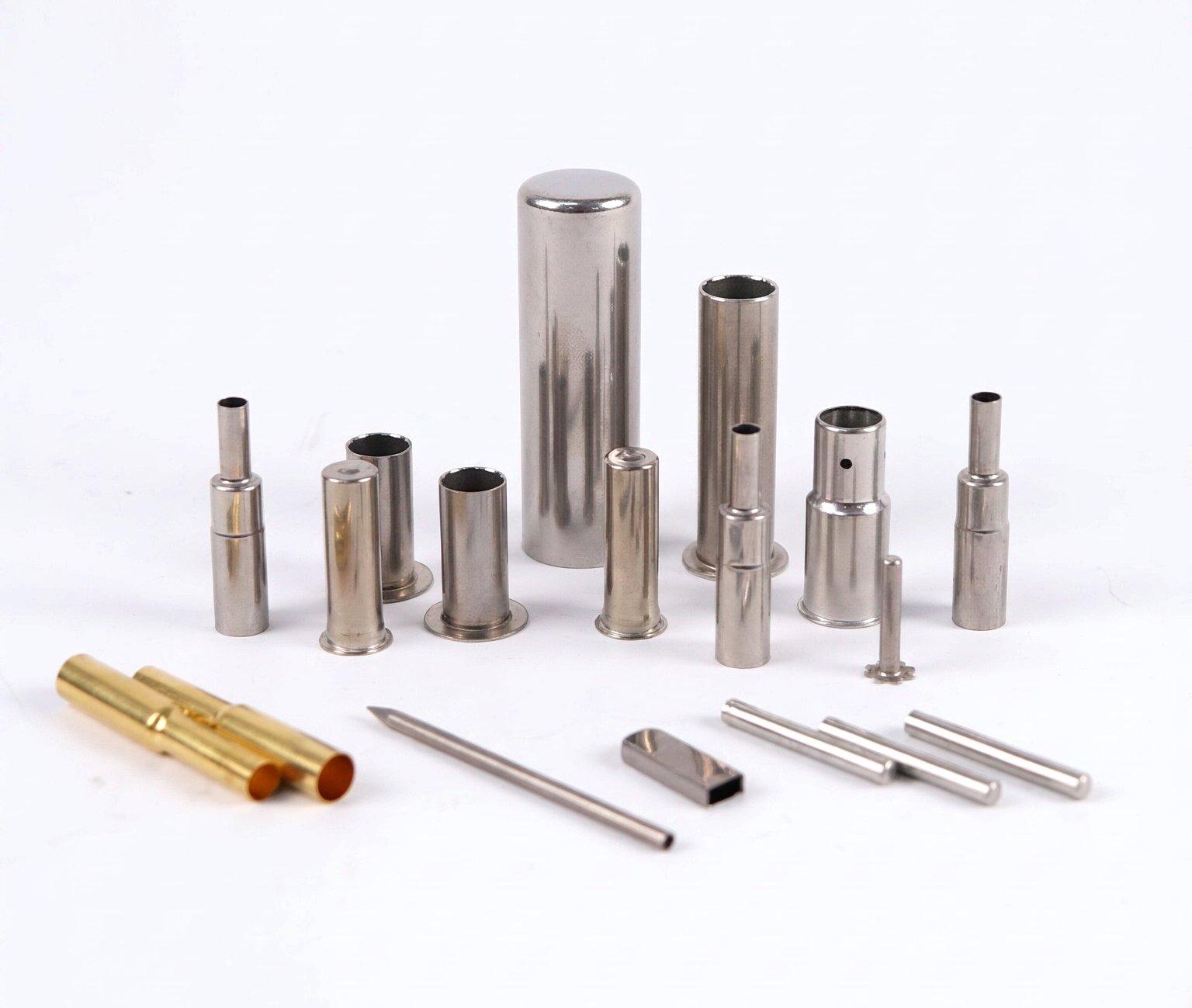
A stamped and deep-drawn stainless steel sleeve is a part described by two processes rather than by one, and on this part the interesting question is which process does what – because the answer determines whether the tolerances are achievable at all, and it is not obvious from the description.
Tube drawing, straightening and turning in one flow, on drawing lines with annealing and finish-turning cells, at +/-0.02 mm on fitted diameters and +/-0.1 mm on formed ends, with finer bands confirmed from capability data. So the tight band is on the fitted diameters and the formed ends are at the loose band – and on a part that mixes processes, the tolerance scheme is really a map of which operation owns which feature.
Why a part ends up with two processes
- Drawing is for round, axisymmetric, thin-wall forms. It is fast, consistent, and cheap per part in volume, and it produces a wall whose properties are the material’s.
- Stamping or pressing is for flat patterns and shallow forms. A deep-drawn cup and a stamped flange are different products, and the flanges on a stamped bracket are made by bending rather than by drawing.
- Machining is for everything the first two cannot reach – a bore to a size, a thread, a seal face, a non-round feature, a feature that has to be coaxial with another.
So a part described as a sleeve with stamping and deep drawing is almost always a hybrid: a drawn or stamped body for the volume, and machined features for the interfaces. And the tolerance scheme should follow that split, which is exactly what the scheme on this page does – the tight band on the fitted diameters is the machined work, and the loose band on the formed ends is the draw’s output.
Where the two processes meet, and that is the hard part
- The junction between a machined feature and a formed body is where the part’s accuracy is decided, because the two are made with the part held differently and their axes will not be exactly aligned.
- And the formed body’s wall condition matters at that junction. A drawn body carries residual stress and springback, so a machined feature referenced to the body’s as-drawn state will move when the machining releases the stress.
- So on a hybrid part the sequence is not negotiable: form, straighten, anneal if required, stress-relieve where precision demands it, then machine. And the reverse sequence produces a part that measures correctly on the machine and not afterwards.
Fitted diameters, and what they fit to
At +/-0.02 mm, the fitted diameters are the part’s interfaces, and on a sleeve they are likely a spigot, a thread, or a gland. Three points.
- A fitted diameter is a fit, not a size, and it should be stated as one with the mating part named. Where the mating part belongs to the customer, that fit has to be agreed rather than chosen.
- Concentricity between the fitted diameters is more important than their individual sizes, because a sleeve that locates by two features needs them coaxial and it does not care whether each is a tenth of a millimetre over or under.
- And the machining must not distort the formed body. On a thin-wall drawn sleeve, machining a feature to a tight tolerance can leave the part distorted – and the distortion shows up as the diameter being right at the cut and wrong fifty millimetres away. So the fixturing and the wall’s stiffness around the machined feature are part of achieving the tolerance.
Formed ends, and the band that reflects the process
At +/-0.1 mm the formed ends are the draw’s and the stamp’s output, and the reasons are the ones that recur across this section.
- Springback. A formed feature will not hold the tool’s angle, and the variation is a function of the material’s condition and the tool’s wear rather than of the machine.
- Thinning at the corners. The most heavily worked metal on the part, and it is usually the thinnest section, which makes it both a forming concern and a pressure or a strength concern.
- And if the part is stamped as well as drawn, the stamping’s own variation adds to this – so a part with both processes has a looser formed band than one with only drawing.
A hybrid part carries a fourth consideration beyond the usual three
Stock covers carbon steel (SPCC / DC01), 304 / 316 stainless steel, aluminium and brass, with mill certificates and heat numbers accompanying the first article. On a hybrid part the material has a fourth consideration beyond the three usual ones.
- Corrosion, from the process the sleeve sees – 316L for chloride-bearing and for cleaning regimes.
- Strength, if it is a pressure boundary or a wear part.
- Formability, because two processes have to be applied to it. A material that draws well but stamps poorly, or that anneals between processes and changes dimension, will make the part inconsistent. On a hybrid part the material’s behaviour across processes is the thing to check.
- And on stainless steel, the heat-affected zone question if the two processes are joined by welding or brazing. A hybrid that is welded after forming has three heat-affected regions, and on a 316L part the grade’s L status matters for all of them.
A hybrid part has two materials, and each needs its own finish decision
Zinc, nickel or chrome plating, anodising, passivation or e-coat, with alternatives quoted alongside the quotation and samples approved in writing. Four items on a hybrid part.
- The fitted diameters and any sealing face, unmasked – and on a hybrid part there are more of these than on a single-process part, which makes the masking list more important and more likely to be got wrong.
- The formed body’s exterior, where the finish is conventional.
- The interior, where the part carries a fluid or a fill – and on a drawn or stamped interior this is a cleanliness requirement that a general finish callout does not address.
- And the process order relative to the finish. A coating on a formed part and a coating on a machined part are different operations, and on a hybrid part the route has to specify which comes first, because a coating applied before machining will be cut through at the machined features.
The fourth flagged item on a hybrid part is the sequencing
+/-0.02 mm on fitted diameters and +/-0.1 mm on formed ends, with finer bands confirmed from capability data. Four items, and the fourth is the sequencing.
- Fitted diameters: size, roundness, concentricity, at the tight band, stated as fits where they are fits.
- Formed ends: geometry, angles, radii, lengths, at the loose band, reflecting springback and the fact that two processes contribute variation.
- Wall thickness at named locations, including any corner that is the thinnest section, with the minimum stated.
- And the process sequence, as a requirement: the order of forming, straightening, annealing, stress relief, machining, and finishing – each in the condition in which its dimensions apply. On a hybrid part with two or three processes this single statement is worth more than any tolerance on the drawing, because it tells the shop which dimensions are process outputs and which are the machining’s own work.
On a hybrid part the machined and formed features drift apart
Finer bands confirmed from capability data before quoting. Three items.
- Dimensional inspection in the finished condition, after all processes, and not after forming.
- The relationships between the machined features and the formed body, measured together. On a hybrid part this is the measurement that tells you whether the two processes have agreed with each other.
- Wall thickness at the corners and the formed ends, which on a two-process part is where the variation accumulates.
- And a functional check where the part carries a fluid, a fill or an element – because on a hybrid part the combination of two processes’ outputs is a functional question and no dimensional inspection tests it.
Does this part really need two processes, or has it ended up with two because
Does this part really need two processes, or has it ended up with two because it was drawn and then something was added to it? It is worth asking because the two processes cost two toolings, two sequences, two sets of tolerances, and an interaction between them that nobody owns. The commonest version of this is a drawn body that grew a machined boss, or a stamped part that needed a bore to a size – and in both cases the answer may be a single process with a different geometry. Where both are genuinely needed, the second question is which process owns the critical dimensions: if the machining owns them, the drawing’s tolerance scheme is fine and the sequencing matters most; if the forming owns them – which happens when the part is mostly drawn and the machined features are incidental – then the formed band should be tighter than it usually is and the machined features should be dimensioned to suit the formed body rather than the other way round. Which of those two situations applies is the difference between a part whose tolerances add up and a part where the two processes are quietly disagreeing with each other in production.
Deep Drawn Tubes & Sleeves is the parent range for parts like this one; the overview page gathers the tooling logic, finishing options and tolerance notes that apply across the family.
Specifications
| Item | Stamped and Deep-Drawn Stainless Steel Sleeves |
|---|---|
| Brand | AUNOV |
| Designing | DFM feedback accompanies the quotation, so surprises are caught before the die is cut. |
| Tooling | Die design and toolmaking stay in house, so no tooling step is outsourced, and first-article timing is measured from the tooling start date. |
| Samples | First articles go out with dimensional data and material certification. |
| Materials | Stock covers carbon steel (SPCC / DC01), 304 / 316 stainless steel, aluminium and brass; mill certificates and heat numbers accompany the first article. |
| Surface finish | Zinc, nickel or chrome plating, anodising, passivation or e-coat; alternatives quoted with the quotation, samples approved in writing. |
| Processing | Tube drawing, straightening and turning in one flow; every stage is logged against your part number. |
| Equipment | Tube drawing lines with annealing and finish-turning cells, with CNC turning centres for secondary operations and CMM inspection. |
| Tolerance | +/-0.02 mm on fitted diameters, +/-0.1 mm on formed ends; finer bands confirmed from capability data before quoting. |
| Delivery terms | Shipping terms are set with the order: FOB, CIF or DDP, T/T or L/C, door delivery quoted. |
Related Products


Request a Quote for This Part
Send a drawing or sketch — get material advice, tooling cost and a per-piece price within 24 hours (working days).