

A drawn NTC sensor housing is two products in one piece of metal. It is a deep-drawn shell, which means its walls, its closed end and its corner radii were produced by a press, and it is a machined part, which means its sealing faces, its threads and any seats were produced by a lathe. Those two processes have completely different behaviours and they meet on this part.
The meeting point is where all the engineering on this page is. And the general rule is worth stating before anything else: the drawn features cannot be held to a machined tolerance, and the drawing has to be honest about which is which.
What the press produces and what the lathe produces
| Feature | Process | What governs its accuracy |
|---|---|---|
| Wall thickness | Drawing | The blank’s thickness and its thickness tolerance, plus the material’s springback |
| Open diameter | Drawing | The die’s diameter and its wear, plus the material’s springback |
| Corner radii | Drawing | The punch and die radii, and the material’s behaviour in the bend |
| Closed end thickness | Drawing | Material’s thinning behaviour at the punch nose, which is the thinnest point on the part |
| Sealing face | Machining | The machine and the tool |
| Thread | Machining | The machine, the tool, and the material’s work-hardening |
| Seat or bore | Machining | The machine, and the roundness of the setup |
So a drawing that writes a single tolerance across the whole part is either going to be very loose on the machined features or going to be an unachievable promise on the drawn ones. The tolerance scheme has to be split, and the split should be visible on the drawing.
Sealing faces, because this is where the sensor fails
An NTC housing’s job is to keep the sensing element in contact with the outside world through a controlled thermal path, and to keep everything else out. The sealing faces are what do both, and they are the tightest requirement on the part.
- Flatness on the sealing face, over its full area, and it is not a general note. On a sensor housing the sealing face may be a gland where an O-ring closes, or a face where a gasket sits, or a welded closure. Whichever it is, the face has to be flat enough that the seal’s compression is even.
- Perpendicularity of the sealing face to the housing’s axis. A face that is not square will seal unevenly around its circumference, and on a sensor housing the effect is a leak path on one side.
- The sealing face’s finish, with a convention, and this is a genuine specification on a surface that a seal has to sit on. A machined face with visible tool witness is not a good sealing surface and a seal will not conform to it uniformly.
- The face’s position along the axis, stated from a named datum, because on a sensor housing the assembly length determines how the element is compressed inside. This is a coordination dimension with the sensor’s assembly and it is usually owned by the sensor’s designer, not by the housing’s.
The interior, which is invisible and decides the accuracy
An NTC sensor works by having the element’s temperature follow the process temperature through the housing wall. The wall is the thermal path, and the wall’s characteristics are set by the drawing process. Three items.
- Wall thickness, and its variation. This is the housing’s primary functional specification and it comes from the blank. The wall thickness tolerance is a stock property and it should be stated on the drawing as a material requirement rather than as a machined tolerance. Where the wall is thicker, the sensor is less responsive; where it is thinner, more responsive and less robust.
- Thinning at the closed end. This is the deep-drawing mechanism that is most often overlooked on a sensor housing. When a blank is drawn into a cup, the metal at the punch nose stretches and thins, and the closed end becomes the thinnest part of the wall. On a sensor housing the closed end is often also where the element sits or where the thermal path is most sensitive, so the thinning is a functional specification and not just a manufacturing note. The drawing should state a minimum wall at the closed end, and it should be checked there.
- The internal geometry at the corner. A deep-drawn corner is a bend radius, and a tight bend radius on a thin wall is a place where the metal has been worked hardest. On a housing whose interior will later carry a potted or sealed element, the corner’s condition matters for the potting’s adhesion and for the wall’s integrity.
Stainless Steel, and the grade choice is a thermal decision as well as a corrosion one
Stock runs to carbon steel, 304 and 316 stainless steel, aluminium and brass, with special grades sourced when volumes justify. On a sensor housing the material has three jobs, and they do not all point the same way.
- Corrosion, from the process the sensor is measuring. 304 for general service; 316L for anything chloride-bearing, for a food or pharmaceutical application, or for a cleaning regime. And the L grade wherever there is welding or heat input, which on a housing with a welded closure is a real consideration.
- Thermal conductivity, which is the one that is easy to miss. Stainless Steel conducts heat roughly twenty times worse than aluminium. A stainless steel sensor housing is thermally slower than an aluminium one of the same geometry, which means the sensor’s response time is worse. This is sometimes the correct trade – a slower sensor is often a steadier reading – and sometimes it is a fault, and it should be a decision. On a fast-response application, or where the sensor is measuring a small feature’s temperature, the housing’s material can dominate the measurement.
- Work-hardening, which is a machining consequence. Austenitic stainless steel hardens as it is cut, which is why a drawn-and-then-machined stainless steel housing needs continuous cutting, positive tooling and rigid workholding. It is also why the machined features should be machined last and why the part should not be re-chucked after a critical feature.
And where an aluminium housing is used, it is usually for thermal reasons and it brings a specific consequence: aluminium expands about twice as fast as steel, so a stainless steel sensor’s leads, wires or terminals in an aluminium housing see differential movement with temperature. That is a real design consideration on a sensor assembly and it belongs at the enquiry.
On this thermowell the finish question is only the face and the thread
Plating, powder coating, anodising or polishing per the print, with the agreed finish travelling with the part number. On this part the finish requirement is narrow and it is almost entirely about the sealing face and the thread.
- The sealing face must be unmasked and preferably polished. A plated or passivated face that has been ground will work; a face that has been coated and not masked will not seal.
- The thread must be masked or specified post-finish with an allowance. On stainless steel, passivation is the correct treatment and plating is not.
- Where a weld closure is specified – a welded hermetic sensor housing is a common design – the weld’s requirement is that it be a continuous, leak-tight, hermetic closure. The weld’s geometry is a functional specification and it needs to be described: a circumferential weld with a stated penetration and a stated absence of inclusions. On a small hermetic housing this is the difference between a sensor that works for years and one that slowly loses its seal.
- Passivation, on stainless steel, is not optional wherever the part will be in a corrosive or a clean service, because drawing and machining both remove the passive film.
Why the sealing face and the drawn profile differ by a factor of five
+/-0.01 mm on sealing faces and +/-0.05 mm on drawn profiles, with finer bands confirmed from capability data. That split is exactly right and it is worth explaining why the two bands differ by a factor of five.
- Sealing faces at the tight band: flatness, perpendicularity, and position along the axis, all measured against a named datum.
- Drawn profiles at the loose band: open diameter, wall thickness, and the general outline, because these come from the material’s behaviour through the press and no amount of process control will make them repeatable to a band of a few hundredths.
- Threads: class and pitch diameter, gauged, per the thread standard. A thread on a sensor housing seals the housing to the sensor’s own stem, and its class determines whether it seals.
- Concentricity of the machined features to the drawn axis. This is the tolerance unique to a drawn-and-machined part, and it is worth stating: the machined features’ axis and the drawn bore’s axis have to agree, because they were made in different operations with the part held differently. On a sensor housing this is what keeps the element aligned with the sensor’s internal geometry.
- Wall thickness at the closed end, as a minimum, and this is the one that a drawing that only lists general tolerances will miss.
Side wall and closed-end wall are two different minimums to check
- Sealing face flatness, perpendicularity and finish, on every part. This is the item that cannot be sampled and it is the one that decides whether the sensor seals.
- Wall thickness at the side and at the closed end, measured separately, with the closed end’s value compared against the stated minimum.
- Concentricity of the machined features to the drawn axis, measured on the CMM.
- Thread gauging, where threaded.
- A functional leak or hermeticity test. On a sealed or welded sensor housing this is the only test that tests the specification and it is quick. On a hermetic welded closure it is a helium leak test or an equivalent, and it should be done on every part where the sensor’s specification requires hermeticity.
- In-process checks between stages rather than only at the end, because the drawing operation and the machining are both slow-drift operations and a batch can be entirely within tolerance and entirely at the wrong end of the wear band.
- Batch records filed so a repeat order starts from approved data – and on a sensor housing this matters more than on most parts, because the housing’s wall thickness and the element’s response are coupled, and a repeat order with a different wall will produce a sensor with different response characteristics.
How fast the sensor must respond, and what it measures
How fast does the sensor have to respond, and what is it measuring? Those two answers decide the housing’s material and its wall thickness, and they are almost never established before the housing is specified. A sensor measuring a slow-changing tank temperature can have a thick wall, a stainless steel housing, and a slow response, and it will be more stable and more robust for it. A sensor measuring a small feature’s temperature, or a fast transient, needs a thin wall and a thermally conductive housing, and the difference in response time between a thick stainless steel wall and a thin aluminium one can be an order of magnitude. Then the second question: is the closure welded or sealed, and does it have to be hermetic? A hermetically welded housing is a different manufacturing question from a gasketed one and it has a different documentation burden. And the third: does the sensor have a lead wire, a terminal, or a connector, because that changes how the housing is closed – a wire-through housing is a different seal from a connector-mount housing, and the wire’s insulation and the seal around it is its own design. Three answers, and they decide the material, the wall, the closure and the test. None of them require a drawing and all of them change the part.
Parts like this one sit under the Sensor Housings range, whose overview page gathers the tooling logic, finishing options and tolerance notes shared across the family.
Specifications
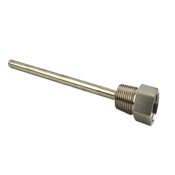
| Item | Stainless Steel Stepped Thermowell Housing, Closed End |
|---|---|
| Brand | AUNOV |
| Designing | Made to your 2D/3D drawings – non-standard features are feasibility-checked at quotation stage. |
| Tooling | Tooling is built to the drawing and held against your part number for the life of the part. |
| Samples | First-article samples ship with a dimensional report and material certificate, so the sample is retained as the master, and the signed sample is kept for future reorders. |
| Materials | Stock runs to carbon steel, 304 / 316 stainless steel, aluminium and brass; special grades are sourced to the drawing when volumes justify. |
| Surface finish | Plating, powder coating, anodising or polishing, per the print; the agreed finish travels with the part number. |
| Processing | The drawn shell gets machined seats and threads where the print calls for them, and batch records are filed so a repeat order starts from approved data. |
| Equipment | Hydraulic presses for drawing, with CNC turning for finishing, backed by CNC turning centres and a climate-controlled inspection room. |
| Tolerance | +/-0.01 mm on sealing faces, +/-0.05 mm on drawn profiles; finer bands confirmed from capability data before quoting. |
| Delivery terms | CIF or DDP, with FOB available, T/T with deposit and L/C for larger runs; call-off schedules are supported. |
Related Products



Frequently Asked Questions
Why is this housing two manufacturing processes in one piece of metal?
The shell is deep drawn, so its walls, closed end and corner radii come from a press, while the sealing faces, threads and seats are turned on a lathe. Those two processes have different accuracies and they meet on the part, so the drawing has to state which feature is drawn and which is turned.
Why do the sealing face and the drawn profile carry different tolerances?
The sealing face is a machined feature and the drawn profile is the material’s own variation, which no amount of process control can repeat to a few hundredths. So the sealing face sits at +/-0.01 mm and the drawn profile at +/-0.05 mm, and the five-times tolerance split reflects two different accuracy regimes.
Why is the grade choice a thermal decision as much as a corrosion one?
Stainless steel conducts heat far worse than aluminium, so a stainless steel housing is thermally slower and the material can dominate a fast-response measurement. The grade also follows the fluid and the response the measurement needs – 316L for anything chloride-bearing, food, pharmaceutical or welded – and the choice should be made, not left to default.
How is a welded closure actually verified?
A hermetic welded closure is verified by a helium leak test or equivalent on every part where the specification requires it, because that is the only test that proves the sealed boundary. On a sensor housing it is the difference between a unit that works for years and one that slowly loses its seal.
Request a Quote for This Part
Send a drawing or sketch — get material advice, tooling cost and a per-piece price within 24 hours (working days).