

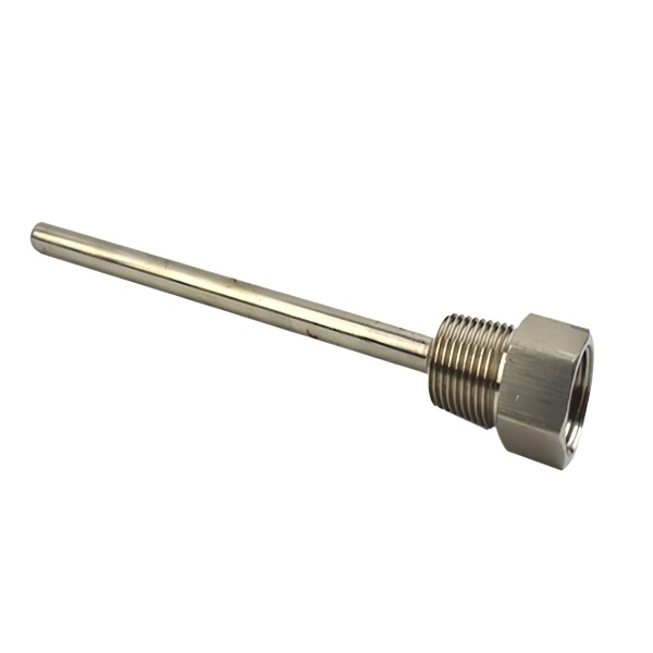
A thermowell probe is not a housing. It is a pressure boundary, a thermal element, and a mounting, and the word “thermowell” describes only the first of those. Getting the word wrong is why this part is so often specified as a tube with a thread, and why so many of them do not measure what they were supposed to.
On this page the argument is that the three functions have one shared constraint – the wall – and that everything about a thermowell follows from what has to happen to a wall between a hot fluid and a cool instrument.
Three functions, one wall
It holds the process out
A thermowell is a pressure boundary. The process fluid is inside it, at whatever pressure and temperature the process runs, and the wall carries the difference between that and whatever is outside. This is the part everyone thinks about, and on a well-designed thermowell it is the part that is easiest, because the wall thickness for pressure is a straightforward calculation.
It conducts the temperature in
Heat has to travel through the wall, from the process fluid to the sensor or the fill inside the thermowell. So the wall is a thermal element, and a thick wall is a good pressure boundary and a poor thermal one. That conflict is the whole design.
It isolates the instrument
The sensor inside the thermowell is expensive, and often not chemically compatible with the process, and sometimes at a ground potential the instrument cannot tolerate. So the wall also has to isolate. And the cheapest way to isolate and to make a good pressure boundary is the same thing: more metal. So isolation and thermal performance pull in the same direction as the pressure boundary does, which means they are all three pulling toward a thick wall and the thermowell’s designer is left with one lever.
- The pressure calculation sets a minimum wall. Below this it fails, and no accuracy argument survives a leak.
- The thermal performance sets a maximum useful wall. Beyond this, extra metal only adds lag.
- The process’s chemistry sets whether isolation is even required. On a benign process a thin single-alloy wall may be perfectly adequate. On a corrosive or a high-temperature process the isolation requirement can dominate and drive the wall up regardless.
- And the insertion depth sets how much of the wall is actually in the thermal path, which is the one lever that is free.
Insertion depth, which is the free accuracy
The accuracy of a thermowell is dominated by the conduction along the wall from the process tip toward the mounting end. The sensor reads somewhere between the process temperature and the ambient temperature, displaced toward the process. Three design responses, in increasing order of how much they cost.
- Insert deeper. The single most effective change and it costs nothing but a longer part. If the immersion depth can be increased, the conduction error falls directly, because more of the length is in the process and the ambient has less metal to conduct through.
- Use a thin wall on a low-pressure service. Where the pressure allows it, the wall can be thinner, which improves both response and accuracy. On a high-pressure or a high-temperature service this is not available, and the wall is set by pressure.
- Reduce the ambient’s influence. Where a section of the thermowell is outside the process – at a vessel wall, through a long nozzle – covering or insulating that section reduces the conduction pulling the reading down. This is a real and effective measure and it is frequently absent.
Construction, and the choice that decides most thermowells
Blanking, drawing and piercing in sequence, then machining of sealing faces. A thermowell is made as a tube and closed at one end, and there are three ways to do that, and the choice is more consequential than it looks.
- A drawn closed end. The blank is drawn into a cup and the open end is machined off. This is the economical route and it is very common. Its consequence is that the closed end is thinner than the nominal wall – the punch nose stretched it – and the closed end is both the pressure boundary’s most stressed section and the thermowell’s most thermally sensitive section. So the thinning at the tip is a specification, and it is a minimum.
- A welded closed end. A tube with an end welded on, and the weld ground and finished. This allows a heavier wall and a heavier gauge tube, which is what a high-pressure service needs, and it puts a weld in the pressure boundary. On a high-temperature service the weld’s material and its heat-affected zone become part of the pressure boundary’s integrity.
- A machined solid end. Turned from solid bar. This is the strongest and the most expensive and it is used where the pressure, the temperature or the corrosion demands it. It also allows a thicker tip and a better-supported geometry.
And the tip’s thickness is the trade in its clearest form: a thicker tip holds pressure better and conducts worse. Where the service is hot and the pressure is high, the tip is the section that gets extra material, and that extra material is the accuracy you gave up.
The stepped bore, and what it does to the measurement
+/-0.03 mm on stepped bores, with concentricity per print and finer bands confirmed from capability data. On a thermowell the stepped bore is where the sensor goes, and it is a measurement-critical feature for reasons that are specific to thermowells.
- It positions the sensor, and the position is the accuracy. A thermowell’s accuracy is a function of where the sensor sits relative to the process. Too far out and the reading is dragged toward ambient. Too far in and the sensor sits in the stagnant boundary layer at the wall, where the temperature is not the bulk temperature. So the bore’s depth is a measurement parameter and it is a real one.
- It isolates the sensor from the mounting, which is the thermal isolation, and it does it by creating a dead volume. A step creates an air gap or a stagnant pocket, and that pocket has to reach the process temperature before the reading is stable. So the step’s geometry is a response-time parameter as well.
- Its concentricity matters because a sensor seated eccentrically in the bore is not in the middle of the thermal path, and on a thermowell that is an error that will not average out.
- And its diameter’s effect on accuracy is not obvious. A bore that fits the sensor closely places the sensor near the wall, where the temperature gradient is steepest. A bore that is a loose fit leaves an air gap, which is an insulator and which adds error. So the bore’s diameter is a thermal decision as much as a fit decision.
Material, and the two that go on a thermowell
Stock runs to carbon steel, 304 and 316 stainless steel, aluminium and brass. On a thermowell the material is chosen by three requirements and they sometimes conflict.
- Corrosion, from the process inside. This is the one that has to be satisfied first, because the process fluid is in contact with the whole interior. 316L for anything chloride-bearing, and the L grade if the closed end is welded. 304 for a benign process.
- Strength, at temperature. A thermowell in a high-temperature service needs an alloy that does not lose too much at temperature, and austenitic stainless steel is the normal answer because it retains its strength better than ferritic grades.
- And conductivity, which is the one that is often ignored. A thermowell’s wall is the thermal path, and stainless steel’s poor conductivity is why thermowells are slow. On a fast-response application, or where the accuracy requirement is tight, the options are a thin wall – where pressure allows – or a different material, or a thermally conductive insert, and each of those is a real trade against the pressure requirement.
- Brass appears on low-pressure, moderate-temperature thermowells and is a good answer there, because its conductivity is several times better than stainless steel’s. Its limit on a hot or a chemically aggressive service is the same as everywhere else on this site.
On a thermowell the sealing face and thread dominate the finish decision
Surface treatment matched to the duty, with alternatives quoted alongside the quotation and samples approved in writing. On a thermowell the finish question is narrow and one item dominates.
- The sealing face and any thread, unmasked. The same rule as everywhere else on this site, and on a thermowell the sealing face is where the process meets the instrument so a plated seal is a leak path and a plated thread is a fit change.
- The exterior, coated or coated-and-wrapped where the process requires it. A thermowell in a corrosive process is sometimes coated on the outside as well as being made of a resistant alloy, and where the coating is a thermal requirement rather than a corrosion one – a high-emissivity coating for a radiation service – it is a functional specification with a real and measurable effect.
- And the interior, which on a hygienic or a pharmaceutical service is the product surface. It has its own finish requirement, and it is a different requirement from the exterior’s, and a general plating or coating callout on a thermowell does not address it.
What goes on the drawing
- The service: the fluid, its temperature, its pressure, and its chemistry. Four things, and they decide the material, the wall, the tip’s construction and the certification.
- The immersion depth required in service, which is not the same as the overall length and is the number that decides the accuracy.
- The accuracy requirement, and the conditions it is claimed at – a thermowell’s accuracy is quoted at a power level or a flow rate, and without that the claim is meaningless.
- The tip’s minimum wall, and whether the tip is drawn, welded or machined.
- The stepped bore’s diameter, depth and concentricity, and which sensor is intended to sit in it.
- Any exterior covering or coating, as a functional specification rather than a finish note.
- The mounting’s thread and its sealing method, and whether it seals on the thread, on a face, or on a compression fitting.
- Whether the process side needs to be cleanable, and if so to what regime.
The fluid, its temperature and its pressure decide whether this is makeable
What is the fluid, and at what temperature and pressure does it run? Those three answers decide the material, the wall’s thickness, the tip’s construction and whether the accuracy requirement can be met at all. The case where they most need to be asked is a high-pressure steam or a high-temperature process, where the pressure calculation sets a thick wall and the thick wall sets a slow response, and the design is a negotiation between two requirements that cannot both be satisfied. In that case the answers determine whether the answer is a machined solid, a heavier gauge tube with a welded tip, or a thermowell with a thermally conductive insert – and all three are legitimate, and which one is right depends entirely on the fluid and the numbers. There is also a question that gets missed on thermowells specifically: is the accuracy claimed at a stated flow rate or power level? Because a thermowell’s error depends on how fast the process is moving past it, and a thermowell specified without that condition is a thermowell whose accuracy claim cannot be checked – which means it is not a specification.
Sensor Housings is the range this part sits under; the overview page pulls together the tooling logic, finishing options and tolerance notes that apply across the family.
Specifications
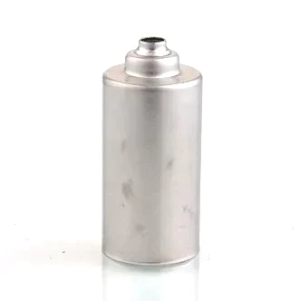
| Item | Stainless Steel Short Sensor Cup with Center Bore |
|---|---|
| Brand | AUNOV |
| Designing | Driven by your drawing or a physical sample – a manufacturability review comes back with the quotation; changes are priced before they are made. |
| Tooling | Die design and toolmaking stay in house, so a die can be re-cut against the approved drawing, and maintenance is tracked against the part number. |
| Samples | Pre-production samples come with a full inspection report, so the sample is retained as the master, and mass production is gated on that approval. |
| Materials | Stock runs to carbon steel, 304 / 316 stainless steel, aluminium and brass; the final grade is fixed with the drawing review. |
| Surface finish | Plating, coating or polishing are matched to the duty; any alternative is quoted alongside the quotation, and sample approval is given in writing. |
| Processing | Blanking, drawing and piercing in sequence, then machining of sealing faces; every stage is logged against your part number. |
| Equipment | Deep drawing presses plus CNC turning centres for machined faces; first articles and batch samples are checked on the CMM. |
| Tolerance | +/-0.03 mm on stepped bores, concentricity per print; finer bands confirmed from capability data before quoting. |
| Delivery terms | FOB, with DDP offered for EU and US addresses, payment by T/T, L/C at sight or D/P; call-off schedules are supported. |
Related Products

Frequently Asked Questions
Why is a thermowell a pressure boundary rather than just a protective tube?
Because it has to hold the process out, conduct the temperature in, and isolate an expensive instrument that may be at the wrong ground potential. Getting the word wrong is why this part is so often ordered as a threaded tube and then fails to measure what it was meant to. Because pressure, isolation and heat transfer all pull the same way, all three functions pull toward the same thick wall, and the designer is left with only one lever.
What actually sets a thermowell’s measurement accuracy?
Accuracy is dominated by conduction along the wall from the process tip toward the mounting end, not by the sensor inside. A wall thickened for pressure or given extra material at a hot high-pressure tip is accuracy the designer has quietly spent. Heat has to travel through that same wall, so the thermal path and the pressure path are the same piece of metal.
How is the closed end of a thermowell made, and why does the choice matter?
A thermowell is made as a tube closed at one end, and there are three ways to do that. The choice changes tip thickness, the heat-affected zone and where a fatigue crack would start, so it is more consequential than a simple end-cap detail. The three functions still have to be satisfied at that closed tip.
Why is the stepped bore held to +/-0.03 mm with concentricity per print?
The stepped bore is where the sensor sits, which makes it a measurement-critical feature for reasons specific to thermowells. Concentricity per print and finer bands confirmed from capability data keep the element centred in the wall. A bore that is off-centre puts the sensor closer to one face and biases the reading.
Request a Quote for This Part
Send a drawing or sketch — get material advice, tooling cost and a per-piece price within 24 hours (working days).