
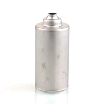
A housing sleeve and a sensor probe are different products that get specified the same way. The probe is the measuring instrument. The housing is the thing that keeps the instrument alive — and it has to do that while being pressed into a hole, clamped, potted, and then sitting at temperature for years next to a device that is generating heat.
The failure mode of a housing is not measurement error. It is the sensor drifting, or the housing corroding through, or the seal opening, and all three of those are consequences of decisions made on a mechanical drawing.
The housing is a thermal sink pointed at the sensor
This is the central fact about a sensor housing and it is regularly designed against. The housing surrounds the probe. Heat flows from the probe into the housing because the housing is a much larger mass at a different temperature. If the housing is at ambient and the probe is measuring something hot, the probe is being pulled toward ambient by its own enclosure.
The magnitude depends on how much of the probe is enclosed:
- Enclosure only at the entry. The housing grips the probe’s leads or a short length of its tail, and the sensing element is well outside the housing body. This is close to ideal and the errors are small.
- Enclosure over part of the body. Common and workable, provided the length of the enclosed portion is short compared with the probe’s sensitive length.
- Enclosure over the sensitive section. The sensor is measured but never sees the process. This is not a sensor housing, it is a sensor blank, and the reading will be permanently wrong by an amount that depends on the housing’s mass and its temperature.
On a drawing, the entry length and the sensitive length need to be distinguishable. Where the probe slides into the housing, the drawing should show where the sensing element ends relative to the housing face, because that single dimension decides whether the part works.
Materials: four that behave completely differently
The four material families available for this geometry are not interchangeable, and the differences show up in three places.
Stainless steel
Corrosion resistant, mechanically strong, and a poor thermal conductor relative to aluminium or brass — around a fifteenth the conductivity of aluminium. On a housing that contacts the process, stainless steel is the default and its thermal performance is a genuine advantage: it does not shunt heat away from the probe. Against that, it is hard to machine, galling-prone at any clamp or thread, and it will bridge the gap between two parts in ways that aluminium will not.
Brass
Excellent thermal conductivity for a copper alloy, easy to machine, and the usual choice where the housing also has to seal against the process or carry a thread. It will dezincify in acidic or chloride-bearing service, and it will corrode under sustained moisture in a way stainless steel will not. It also has a lower melting point, which matters if the assembly is ever potted with a hot-curing compound.
Aluminium
Light, easy to machine, good thermal conductivity. Its weaknesses are galvanic corrosion against copper or stainless steel fasteners in the presence of moisture, and its tendency to gall where it is clamped. Where an aluminium housing is bolted to a stainless steel probe, the joint needs an insulator or the galvanic pair will consume the aluminium preferentially.
Carbon steel
Cheap and strong, and correct where the housing is entirely internal or where the temperature is low and the environment benign. It rusts, it needs a coating, and the coating thickness has to be considered if the housing is in the thermal path.
The important point is that the choice is not only about corrosion. Conductivity, galling tendency, melting point and galvanic compatibility with the probe all enter into it, and the two materials in a sensor assembly touch each other wet in service more often than most assemblies.
Galling is a real failure mode in sensor assemblies
Threaded, clamped and press-fit stainless steel assemblies gall. Galling is not friction — it is adhesive transfer of material between two stainless steel surfaces under load, and the result is a joint that seizes and then tears, taking material from both parts.
The mitigations are well established but each has to be specified rather than assumed:
- Hardness separation. A galling pair is one where both surfaces are in the same hardness band. A 304 housing with a 303 or a hardened stainless steel screw avoids most galling because the harder part cuts rather than smears. Specify hardness on at least one of the pair.
- Lubrication. A dry film or a suitable lubricant prevents metal-to-metal contact and is the cheapest fix. Many galling failures are simply an assembly drawing that did not say so.
- Plating the housing. A nickel or tin plating layer separates the two stainless steel surfaces and eliminates galling. It also gives a defined surface for a seal and improves corrosion resistance, so it is common on this type of part.
- Clearance at the threads. Galls need metal contact. A thread with adequate clearance and a non-locking class will not seize, at the cost of needing a locknut.
- A dissimilar material at the joint. A polymer spacer, a brass bushing or a nylon insert breaks the stainless steel-to-stainless steel pair entirely.
On a housing that will be assembled and disassembled during its service life, this is a decision worth making deliberately at the drawing stage, because a seized housing on a probe that has been correctly calibrated is a scrapped probe.
The press fit: interference without damage
Where the probe is pressed into the housing, the fit has to hold without crushing either part. The variables are:
- Interference. Large enough to retain, small enough that the probe is not crushed. A thin-wall probe deforms rather than cracks under excess interference, and a deformed probe changes its thermal path.
- Lead relief. This is the detail that most often causes the failure. If the leads are pinched at the entry, they fatigue at the pinch and break inside the housing — which produces an intermittent open circuit that looks like an intermittent sensor fault.
- Hole geometry. The entry needs a lead relief, which means either a counterbore, a step, or a lead exit hole offset from the press-fit zone. This is a design feature, not a manufacturing detail, and it has to appear on the drawing.
- Material ductility at insertion. A probe tube in a hardened condition will not tolerate a press fit. If press fitting is the design, the temper condition at the press zone is a specified requirement.
The correct drawing for a press-fit housing shows the leads exiting through their own opening, with the geometry making clear that they are never clamped. A housing drawing that shows only a bore gives the assembler no way to know this and every unit will be built the same wrong way.
How the assembly gets sealed
An enclosed sensor has to be protected from moisture, and the choice is between a gasket, a potted joint and a hermetic weld or brazed closure.
Gasket. Serviceable and reversible, and the least reliable long term. Elastomer gaskets harden, take a compression set and eventually allow ingress. For a low-duty or serviceable application this is the right answer.
Potting. The joint is filled with a filled epoxy or silicone after assembly. It seals well, protects the leads and suppresses movement, and it makes the assembly non-serviceable. Two constraints follow. The pot life and cure schedule have to fit the production flow, and the filler’s thermal conductivity becomes part of the sensor’s thermal path if it reaches the sensing element. Potting that encroaches on the sensitive section will shift the reading.
Hermetic closure. Welded or brazed, gives a true seal and is the correct answer wherever the assembly sees a wide temperature range or has to hold refrigerant or pressure. It costs more and it is a one-way assembly.
On a drawing, the sealing method should be named, because it determines both the assembly sequence and whether the part can ever be repaired.
Inspection points that actually discriminate
- Bore diameter and position relative to the sensing zone. The single most important functional dimension on the part.
- Lead exit geometry. Position and size of the relief, confirmed visually on the first article and by a gauge thereafter.
- Entry chamfer and lead relief form. A sharp entry is a lead cutter and is invisible after assembly.
- Surface finish at the press-fit zone. Excessively rough surfaces increase the required interference and increase the risk of galling.
- Coating thickness and coverage. Particularly at the threads and the lead exit, where a thick coating reduces clearance and can bridge a seal face.
- Hardness, where the drawing calls for hardness separation. Not usually a production check, but always a first-article one if it is specified.
Questions worth asking about a sensor housing drawing
- Where does the sensing element end relative to the housing face, and is that dimension stated?
- Is the entry configured so the leads are never clamped — counterbore, step, or offset exit?
- Which material is specified for the housing, and against which material is it galvanically and galling-wise paired?
- Is a hardness requirement placed on one of the pair to prevent galling?
- Is the coating specified with its thickness band, and are the threads and lead exits identified as masked or as critical coating surfaces?
- If the probe is pressed in, is the temper condition required at the press zone, and is the lead relief dimensioned?
- Is the sealing method named — gasket, potted or hermetic — and does the drawing show the seal geometry?
- Is the housing marked, laser-marked or otherwise identified once assembled, and does that identification survive the sealing process?
That final point is a small thing with a large effect on service. Once a sensor is potted into a housing, the only way to know what it is without dismantling it is the marking. If the marking is applied before potting and is obscured by it, or applied after and is unreadable on a small cylindrical surface, the assembly has to be broken to be identified — which usually means scrapped.
Deep Drawn Tubes & Sleeves is the parent range for parts like this one; the overview page gathers the tooling logic, finishing options and tolerance notes that apply across the family.
Specifications
| Item | Drawn Can with Stepped Neck, Closed Body |
|---|---|
| Brand | AUNOV |
| Designing | Driven by your drawing or a physical sample – unusual walls, threads or tolerances are feasibility-checked first; the same drawing is used for every repeat order. |
| Tooling | Tooling is built and held under your part number, so no tooling step is outsourced, and maintenance is tracked against the part number. |
| Samples | Sample lead time is quoted with the order, and the approved sample governs the run. |
| Materials | Stock runs to carbon steel, 304 / 316 stainless steel, aluminium and brass; material substitutes are proposed only with your written approval. |
| Surface finish | Duty decides the surface treatment, plating, coating or polishing; we quote alternatives with the quotation and approve samples in writing. |
| Processing | Tube drawing with precision turning on critical diameters; first articles verify the whole flow before the run is released. |
| Equipment | Drawn-tube benches, in-line annealing and CNC turning, backed by CNC turning centres and a climate-controlled inspection room. |
| Tolerance | +/-0.05 mm on bore, wall thickness band confirmed at first article; critical dimensions carry CMM data with the shipment. |
| Delivery terms | FOB Ningbo or Shanghai, T/T or L/C, with D/P accepted on repeat business; repeat orders reuse the approved first article. |
Related Products



Frequently Asked Questions
Why is a housing sleeve not the same product as the probe?
The probe is the measuring instrument; the housing is the thing that keeps the instrument alive while being pressed into a hole, clamped, potted, and sitting at temperature for years next to a device that generates heat. The housing is a thermal sink pointed at the sensor, so its material choice is a thermal and mechanical decision at once. A housing that contacts the process defaults to stainless steel, whose poor conductivity is a genuine advantage because it does not shunt heat away from the probe.
How do the four materials behave differently?
Stainless steel is corrosion resistant and strong but conducts around a fifteenth of aluminium and is galling-prone at any clamp or thread. Brass machines easily and seals well but will dezincify in acidic or chloride-bearing service. Aluminium conducts well but suffers galvanic corrosion against copper or stainless steel fasteners and galls where clamped. Carbon steel is the fourth, and each implies a different sealing and assembly route.
Why is galling a real failure mode in sensor assemblies?
Galling is not friction, it is adhesive transfer of material between two stainless steel surfaces under load, and the result is a joint that seizes and then tears, taking material from both parts. Threaded, clamped and press-fit stainless steel assemblies gall, and a drawing that shows only a bore gives the assembler no way to know this. An enclosed sensor then has to be protected from moisture by a gasket, a potted joint or a hermetic weld or brazed closure, and elastomer gaskets harden and take a compression set over time.
What should the press fit and the drawing settle?
The press fit is interference without damage, so the fit class and the lead-in both have to be on the drawing. Inspection points that actually discriminate are the ones that catch a galled or out-of-round bore before assembly. Questions worth asking about a sensor housing drawing are which material, which fit, and which seal, because each changes the others.
Request a Quote for This Part
Send a drawing or sketch — get material advice, tooling cost and a per-piece price within 24 hours (working days).