
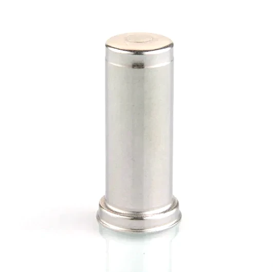
A stainless steel closed sensor sleeve with rim base is a deep-drawn cup whose open end carries a formed rim that acts as the mounting and sealing face. The closed end is the sensing face; the rim base is what clamps it into the assembly and stops it sinking into the bore. The part lives or dies on how flat and true that rim stays after drawing, because the seal depends on it.
Drawn shell with machined seats and threads where the print calls for them, at +/-0.01 mm on sealing faces and +/-0.05 mm on drawn profiles. So the tight band is on the ends – which on a micro capillary is correct, and it is also where all the forming happens.
Why the wall is a strength requirement here
On a capillary of ordinary size, a bend that kinks is a problem because it changes the tube’s behaviour. On a micro capillary, the same bend may simply tear the tube, because the wall’s thickness relative to the bending radius is much greater.
- The bending strain scales with the ratio of the tube’s radius to the wall’s thickness. On a large tube with a thin wall, the outer fibre’s strain at a reasonable bend radius is a small fraction of the material’s limit. On a micro capillary – a 0.5 mm bore with a 0.1 mm wall, for example – the same bend radius produces a strain several times higher, and the tube either work-hardens and splits or it fails.
- So the minimum bend radius on a micro capillary is not a comfort margin, it is a survival limit, and it scales with the bore-to-wall ratio rather than with the bore alone. That is the number that has to be on the drawing, and it is the number that is most often absent.
- And the forming at the end is the worst bending the tube sees. A flared end, a swaged end, a reduced end, or a formed cone – each of these is a permanent deformation put into a tube whose wall is already thin relative to its size. So the end-forming operation has to be designed with the wall’s strain limit in mind, and that means the tooling’s radius and the forming speed matter.
What the end is for, because that decides what forming it needs
The end of a micro capillary is formed for one of four reasons, and each of them has a different requirement. This is worth separating because the customer’s answer often determines whether the part can be made as drawn.
- Connection to a fitting. A flared end that will be compressed into a compression fitting, or a ferrule that will grip it. The flare’s angle, its length, and the wall’s thickness at the flare are all seal parameters and all functional. And the flare needs enough wall to deform into – on a micro capillary there may not be enough, in which case the design has to change.
- Connection to a soft tube. A barb or a spigot that will be pushed onto a tube. The barb’s diameter and the tube’s bore have to be designed as a pair, and the tube’s material’s elasticity matters as much as the metal’s.
- A sensor attachment. Where the capillary carries an element’s leads and the end is formed to retain or to seal them. Here the forming has to avoid cutting the conductors, which on a micro tube is the real constraint.
- Or a reference measurement. In analytical instrumentation a capillary’s end is sometimes formed to a specific geometry precisely so that it draws or dispenses a defined volume – and on those parts the end’s geometry is the measurement, not a connection.
So the first question on a micro capillary is: what is the formed end for? Because a flare, a barb, and a dispensing geometry need different radii, different wall thicknesses, and different amounts of material at the end.
Wall thickness uniformity, which is harder at this scale
The general requirements on a drawn capillary – the wall’s uniformity along the length, the closed end’s thinning, the corner’s work-hardening – all apply here and all of them are harder to hold.
- A drawn closed end’s thinning is a larger fraction of the wall on a micro tube. The same draw ratio produces a proportionally greater thinning, so the closed end’s minimum wall has to be a real specification and it has to be checked there rather than inferred from the blank.
- The corner’s condition is a bigger problem. The most heavily worked metal on the part, and on a micro tube the corner’s radius may be comparable to the bore, so the corner’s work-hardening and its residual stress occupy a proportionally larger share of the cross-section. That makes the corner a crack initiation site in a way it is not on a larger tube.
- And the wall’s variation along the length, which is acceptable on a big capillary, is a functional variation here. On a micro tube the wall’s thickness affects both the flow resistance and the burst pressure, and a wall that varies by ten per cent is a resistance that varies by ten per cent along the tube.
At this scale the interior cleanliness requirement becomes the whole job
Finish selected from the drawing – plating, coating, anodising or passivation – with the finish inspected with the dimensional report on the first article. On this part the finish has a specific requirement driven by the scale.
- The interior has to be clean, and at this scale cleanliness is harder. Any residue, oil or particulate in a micro bore is a large fraction of its cross-section and it will affect both the flow and – if it is a capillary carrying an analytical sample – the result. So on a micro capillary the interior’s cleanliness is a functional requirement and it should be specified as one.
- And on a formed end, the finish follows the forming. Where the end has been flared or swaged, the surface has been worked, and a coating applied after the forming sits on a work-hardened surface. That is fine for most coatings, but on a corrosion-resistant requirement the passivation has to follow, not precede, the forming.
- Where the bore is a measuring bore, the surface finish is a measurement parameter rather than a cosmetic one, because the bore’s roughness contributes to its effective diameter at this scale.
The same tolerance number means different things at 0.5 and 50 mm
+/-0.01 mm on sealing faces and +/-0.05 mm on drawn profiles, with finer bands confirmed from capability data before quoting. On this part the tolerance scheme has to be read with the scale in mind, because the same numbers mean different things on a 0.5 mm bore and on a 50 mm one.
- Sealing faces at the tight band – the end that seals to the fitting or to the process.
- The bore’s diameter, and on a micro bore this is the dimension that decides the flow. A bore tolerance expressed as a percentage is more meaningful here than one expressed absolutely, and stating it both ways is worth doing.
- The wall’s minimum, stated at the formed end and at the closed end, since those are the two thin sections.
- The formed end’s geometry – its angle, its length, its diameters – as functional dimensions, because on a flare these are seal parameters and on a barb they are the grip parameters.
- And the minimum bend radius for the specific tube, which on a micro capillary is a strength limit rather than a convenience.
Below five millimetres, the measurement method becomes the specification
Batch records filed so a repeat order starts from approved data, with secondary operations on CNC turning centres and inspection on the CMM. On a micro part the inspection plan has an extra problem: the features are getting close to the limits of what can be measured conventionally.
- Bore and wall measured at the ends and in the middle, where the consistency along the length matters.
- The formed end’s geometry measured as an angle, a length and diameters, verified against a master.
- A functional fit check against the mating fitting or tube, on a sample – and on a micro part this is often more informative than any dimensional result, because it tests the wall’s behaviour in a way a micrometer cannot.
- And a leak or flow test, which on a micro capillary is a sensitive measure of whether the wall is continuous – a micro crack that a dimensional check will not find will show up as a flow anomaly.
The wall-to-bore ratio decides whether this capillary is makeable
What is the bore and the wall, and what is the end for? Two questions, and the first one decides whether the part is makeable at all. On a micro capillary the wall-to-bore ratio is the governing number, and if the customer wants a very thin wall on a very small bore then the forming and the bending limits come into it immediately – and the honest answer may be that the end cannot be flared, or that the minimum bend radius is larger than the routing allows. Establishing those two numbers first can save a drawing revision, and it can also be the answer that changes the design from a flarable tube to a tube that is supplied pre-formed or to a completely different construction. The second question – what the end is for – decides the end’s geometry and, on a flare, whether there is enough material at the end to deform into a seal at all. And there is a third question worth asking at the same time, which is about the tube’s own route: where will this capillary be bent, and by whom? Because on a part this thin, a micro capillary that is bent during installation will probably be damaged, and the answer may be that it must be supplied formed to shape with the bend radius stated as a manufacturing requirement rather than an installation guideline.
You will find this part in our Sensor Housings range. Process notes, common materials and inspection points for every product in the family are collected across the sensor housings pages.
Specifications
| Item | Stainless Steel Closed Sensor Sleeve with Rim Base |
|---|---|
| Brand | AUNOV |
| Designing | Send drawings, or send a sample to be measured – DFM notes are returned before any tooling is cut; changes are priced before they are made. |
| Tooling | Our toolroom covers die design, wire-cut EDM and maintenance, so no tooling step is outsourced, and the charge is refundable against agreed volumes. |
| Samples | Sample lead time is quoted with the order, and the approved sample governs the run. |
| Materials | Stock runs to carbon steel, 304 / 316 stainless steel, aluminium and brass; the final grade is fixed with the drawing review. |
| Surface finish | Finish selected from the drawing: plating, coating, anodising or passivation; the finish is inspected with the dimensional report on the first article. |
| Processing | Where the print calls for them, seats and threads are machined into the drawn shell; batch records on file mean repeat orders start from approved data. |
| Equipment | Hydraulic presses for drawing, with CNC turning for finishing; secondary ops run on CNC turning centres, inspection on the CMM. |
| Tolerance | +/-0.01 mm on sealing faces, +/-0.05 mm on drawn profiles; finer bands confirmed from capability data before quoting. |
| Delivery terms | FOB, CIF or DDP per Incoterms 2020, payment by T/T or L/C, quoted in USD or EUR; sea or air freight is quoted to your door. |
Related Products


Frequently Asked Questions
Why is the wall a strength requirement on a micro capillary?
On a micro capillary the wall is a significant fraction of the diameter, so the wall stops behaving as a membrane and starts carrying load as well as carrying fluid. A flare, a barb and a dispensing geometry need different radii, different wall thicknesses and different amounts of material at the end.
What does the end being for decide about its geometry?
What the end is for decides the end’s geometry and, on a flare, whether there is enough material at the end to deform into a seal at all. Drawn shell with machined seats and threads where the print calls for them runs at +/-0.01 mm on sealing faces and +/-0.05 mm on drawn profiles, with finer bands confirmed from capability data before quoting.
Why does the same tolerance number mean different things at 0.5 and 50 mm?
Because on a micro part the features are getting close to the limits of what can be measured conventionally, so the measurement method becomes part of the specification. The general drawn-capillary requirements, wall uniformity along the length, closed-end thinning and corner work-hardening, all apply and are all harder to hold.
What is the bore and the wall, and what is the end for?
Establishing those two numbers first can save a drawing revision, and it can also be the answer that changes the design from a flarable tube to one supplied pre-formed or to a completely different construction. The wall-to-bore ratio decides whether this capillary is makeable.
Request a Quote for This Part
Send a drawing or sketch — get material advice, tooling cost and a per-piece price within 24 hours (working days).