
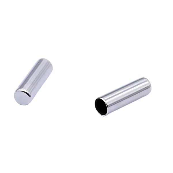
The Deep Drawn Stainless Steel Sensor Sleeve Shells are sensor sleeves produced by deep drawing rather than by turning from bar or cutting from tube, so the whole shell – its wall, its closed end and its depth – is formed from a flat blank in the press. Deep drawing is chosen for these shells because it makes a thin-walled, closed-end sleeve in one continuous process, with no seam and no joint, and it does so at a cost that turning the same shape from solid would never match. The trade is that a deep drawn shell inherits everything the drawing does to the metal: wall thinning that varies along its depth, work-hardening that has to be managed between stages, and a closed end whose thickness is set by the draw rather than by a machining operation. This page covers the drawing, the wall it produces and the closed end it forms.
Deep drawing makes the shell and sets its wall at the same time
When a sleeve is turned from bar, the wall is whatever the machinist leaves; when it is deep drawn, the wall is a consequence of the drawing – it thins where the material stretches and stays thicker where it does not. That means the wall thickness of a drawn shell is not uniform, and it is not freely chosen: it follows from the draw ratio, the blank holder and the number of stages. Understanding that the wall is an output of the process, not an input to it, is the first thing about specifying a drawn shell.
- Wall thickness varies along the depth of the shell, and we predict the thinnest point before committing to the draw.
- The minimum wall is held against the pressure and the handling the shell will see, because the draw decides where it lands.
- Where a uniform wall is required, we discuss whether drawing can deliver it or whether the shape needs a different process.
Wall thinning along the depth is the defining characteristic
As the blank is drawn into the cup, the wall stretches to take the shape, and it stretches unevenly – typically thinning most where the material has travelled furthest and worked hardest. On a deep shell that variation can be significant, and it lands exactly where the shell is most loaded. The thinning is predictable from the draw geometry, so we calculate the worst-case wall and hold the design against that, rather than measuring an average wall and assuming it represents the part.
- We calculate the thinnest wall from the draw geometry and hold the application against that minimum, not the average.
- Wall thickness is spot-checked at several depths on the first article, because the thinning is not uniform.
- Where the thinning is severe, we stage the draw or adjust the geometry so the minimum wall stays above what the shell needs.
Staging and annealing a deep stainless steel shell
Stainless Steel work-hardens fast, and a deep drawn stainless steel shell is drawn hard by definition – the material has been stretched a long way to reach the depth. That hardening both raises the force the next stage needs and pushes the metal toward the tearing limit, so a deep stainless steel shell is almost always staged, with an anneal between stages to restore ductility. Skipping or rushing the anneal is the classic way a deep stainless steel shell ends up cracking at the wall or at the punch radius after it looks fine on the press.
- Deep stainless steel shells are staged, with the reduction per stage held inside what the work-hardened metal can take.
- Interstage annealing restores ductility so the next stage can draw without cracking, and it is scheduled into the route, not improvised.
- After annealing, the scale is removed before the next draw, because scale left in the die raises force and marks the wall.
The closed end is formed by the draw, and its thickness is set by it
The closed end of a drawn shell is not machined – it is the part of the blank that was trapped between the punch and the die and ironed to its final thickness. That means the end thickness is a function of the draw, and a shell that needs a specific end thickness has to get it from the drawing parameters rather than from a facing cut. The end also has to conduct heat to the sensor and, on many shells, form part of the pressure boundary, so its thickness matters functionally and has to be verified where the draw put it.
- Closed-end thickness is set by the draw and verified, because it serves both the thermal path and, often, the pressure boundary.
- The end is checked for roundness and centring, because a draw that closes unevenly leaves the end off the shell axis.
- Where the sensor seats against the end, its internal surface is finished for contact so heat transfers rather than crossing an air gap.
How we verify a deep drawn sensor sleeve shell
Verification on a drawn shell checks the wall that the draw produced, the closed end it formed and the bore the sensor uses, because all three are consequences of the same process.
- Wall thickness: spot-checked at several depths on the first article, with the minimum wall confirmed against the pressure and handling requirement.
- Closed end: thickness, roundness and centring verified, with the internal surface confirmed for sensor contact.
- Bore: diameter, roundness and finish confirmed along the depth, since the sensor seats and reads from the bore.
- Draw record: stage count, reductions and any anneal recorded, so a dimensional drift traces back to the press rather than being guessed at.
- Material certificate per lot confirming the stainless steel grade, with the anneal and passivation records attached.
- Fit check: the sensor inserted and seated, and on the first article the shell confirmed to accept it cleanly before the run.
First articles and retention samples are kept for the programme, and the draw record travels with them, so a repeat shell is drawn to the same verified wall and end. On a part whose wall and closed end are both outputs of the drawing rather than machined features, holding the draw to a verified baseline is what keeps a second batch matching the first in thickness, depth and seating.
Our Sensor Housings range is where this part sits. The sensor housings pages carry the process notes, common materials and inspection points behind every product in the family.
Specifications
| Item | Deep Drawn Stainless Steel Sensor Sleeve Shells |
|---|---|
| Brand | AUNOV |
| Designing | Send drawings, or send a shell sample to be measured, the quotation comes back with a manufacturability review attached. |
| Tooling | Every die designed and built in our toolroom, stored under your part number. |
| Samples | First-article samples ship with dimensional data and material certs. |
| Materials | 304 / 316 stainless steel is the primary stock for this part, alongside carbon steel (SPCC / DC01), aluminium, brass and copper, with the final grade confirmed at the drawing review. |
| Surface finish | Plating, e-coat, powder coating, anodising or passivation, as called out on your print. |
| Processing | Staged deep drawing, with in-line annealing where the draw ratio requires, pierced and finish-machined on the same floor. |
| Equipment | 5-250 T mechanical presses plus 250-500 T hydraulic presses, CNC cells plus a temperature-controlled CMM room. |
| Tolerance | Drawn tolerances held to +/-0.1 mm, with machined features to +/-0.03 mm. |
| Delivery terms | Standard terms FOB, DDP offered to EU and US, T/T or L/C, D/P on repeat business, blanket orders and call-offs supported. |
Frequently Asked Questions
How much machining stock does a drawn sleeve shell need, and where does it go?
Enough to clean up the surfaces that have to interface, and not elsewhere. An as-drawn tolerance of +/-0.1 mm suits surfaces that only need positioning, but a sealing bore, a mating thread or a face that has to seat will usually want metal removed, so stock goes on those surfaces alone. Because wall thickness varies along a drawn shell, that stock has to be allowed at the thinnest place it will be machined from, which is why marking which surfaces get machined achieves more than adding a blanket allowance.
Does interstage annealing do anything besides permit the next draw?
It affects the material condition of the stainless steel as well. Heating leaves an oxide film that has to come off before further processing or finishing, and the thermal cycle has to be considered against corrosion performance afterwards. That is why annealing is planned into the process rather than added when a draw goes badly, and why cleaning and passivation are specified alongside it instead of assumed to happen later.
How should a leak requirement be written when there is no honest number to put on it?
By specifying the test rather than inventing a rate. The temptation is to write a leakage figure on the drawing because it looks rigorous, but unless the product requirement genuinely produces one, the number becomes an inspection argument. Better practice is to state the method that demonstrates soundness – a pressure hold, bubble test or helium detection as appropriate – together with test pressure, dwell time and what counts as pass, leaving numeric sensitivity to whoever owns the product.
Can the closed-end thickness be specified separately from the wall?
Only within limits. Deep drawing sets the end thickness at the same time as the wall, and what the ends up with follows from the draw plan rather than being an independent choice. Where an application genuinely needs more material there than the wall will deliver, it has to come from another route: local addition, a coining or restrike stage to redistribute metal, or a machined end. Saying which surfaces matter most at enquiry is cheaper than finding out later that the end cannot simply be thickened on its own.
Related Products


Request a Quote for This Part
Send a drawing or sketch — get material advice, tooling cost and a per-piece price within 24 hours (working days).