

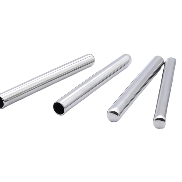
6 x 50 mm: when the dimensions in the title are the whole specification
A 6 x 50 mm temperature sensor housing looks like a specification with almost nothing in it, and for a part in a standard size that is exactly right. The diameter and the length are not features – they are the interface. Everything about this part follows from the fact that 6 mm and 50 mm are numbers that a customer’s bores, fixtures and installation tooling are already built around, and that the housing has to perform as a thermal device rather than merely as a piece of stainless steel.
We deep draw these on hydraulic presses and CNC-finish where tolerances tighten, with in-process checks between stages rather than only at the end. Deep drawing presses plus CNC turning centres for machined faces, with in-house toolmaking keeping dies and fixtures maintained. Turned or milled features to +/-0.01 mm and formed details to +/-0.03 mm, and dimensional reports accompany the first article. Stainless Steel 304 and 316L, pickled and annealed, at 50 mm nominal wall – one grade chosen for the corrosion duty and the formability of this sensor. This page covers what a dimension-specified part still has to decide, and why the thermal requirement is usually the one that matters.
The dimensions are the interface, so their tolerances are critical
On a part named for its size, the size is a fit requirement and the tolerance on it belongs to the customer’s assembly. That changes how it should be drawn:
- Is 6 mm nominal or exact? A tolerance of +0.05 / -0 gives a press-fit part. A tolerance of h-type or a stated band gives a clearance part. The nominal alone does not say which, and the difference matters more than anything else on this drawing.
- Is 50 mm the free length, the overall length including a feature, or the length to a datum face? On a probe housing the length that matters is usually the insertion length – the distance from the mounting face to the tip – and that is a different number from the overall length. Where the part has a crimp or a flange, the distinction is essential.
- Which is the datum for the length? A length measured from a machined face is controllable. A length measured over a drawn tip is a formed dimension and will vary with the draw.
- Does the customer’s tolerance on the bore interact? On a 6 mm part in a 6 mm bore, the housing’s tolerance and the customer’s bore tolerance together determine whether it assembles at all – and on a small diameter the customer’s bore may be the looser of the two.
Quotation follows the print, not a catalogue, and samples are reverse-measured into a controlled drawing – so if you have a physical sample, that measurement produces a drawing that states the actual tolerances rather than nominal dimensions, which on a size-specified part is most of the value.
It is a thermal device, and the wall decides whether it works
A temperature sensor housing has one primary job beyond protection, and that is to conduct heat from the measurement point to the sensing element without adding error. Stainless Steel is a poor thermal conductor compared with copper or aluminium, which is precisely why it is used: the low conductivity provides thermal isolation from the outside world, so the sensor reads the temperature at its tip rather than the temperature of the surroundings. That is a design benefit and it is also a constraint, because the same poor conductivity makes the response time slow.
Three consequences on the drawing:
- Wall thickness is a thermal variable, not just a structural and a forming one. A thinner wall gives faster thermal response and more thermal error from the surroundings; a thicker wall gives better isolation and slower response. The 50 mm nominal wall is a real design parameter here, and the tolerance on it affects the calibration.
- The tip is the measurement point, and its condition matters disproportionately. A drawn tip has a radius and possibly a seam from the draw; the seam location on a probe tip is a real design question, because a seam in the tip can affect both the thermal path and, if the tip must be smooth, the surface.
- Length dilutes nothing. A 50 mm probe is more sensitive to gradients along its length than a 10 mm one. If the sensor is measuring in a vessel with stratification, the insertion length is a design decision about where it reads, not just about how it is held.
Pickled and annealed: what that tells you about the route
The material state named on this part – pickled and annealed stainless steel – is not a finishing instruction. It is a description of the material’s condition and it points at the process:
- Pickled means the surface oxide has been removed by acid treatment. On a drawn part this is a standard step after annealing, because an annealed surface carries an oxide skin, and on stainless steel that skin is what rusts first. Pickling is therefore a functional requirement on any stainless steel housing that will see moisture, and it needs to be stated – not implied by the alloy.
- Annealed means the material is in a soft, ductile, stress-relieved condition. On a part formed by deep drawing this is what makes the forming possible in the first place, and it also means the part arrives with low residual stress, which is good for dimensional stability.
- What it excludes. A cold-worked or hardened stainless steel condition would be specified for a spring or a wear part. On a probe housing it is neither wanted nor possible, since the forming route requires ductility.
The practical point: on a temperature sensor housing the surface condition of the stainless steel is a corrosion requirement, and it is cheap to specify and expensive to retrofit. Pickling and passivation should both appear on the drawing for any part that will be installed in a wet or outdoor environment.
Deep drawn, then CNC-finished only where the tolerance tightens
The route here is deliberately mixed: draw what can be drawn, machine only what has to be machined. That is the right approach for this part, and the design principle behind it is worth stating because it is the same one that applies to most drawn-and-machined work:
- Drawn features get the formed-details band of +/-0.03 mm, and they should be features that do not need tighter – the outer diameter, the general profile, the tip’s overall form.
- Machined features get +/-0.01 mm, and they should be the features that define the interface: the mounting face, the bore, any thread, the crimp or the tip’s sealing feature.
- In-process checks between stages, not only at the end – so a drifting die is caught on the batch rather than discovered at the customer’s inspection.
Where the wall thickens at the base – which happens in a draw, because material accumulates where the flow stops – the transition has to be machined back to a controlled diameter if the customer’s bore is close. That machining is what the tight band is for, and the drawing should show the drawn step and the machined diameter as separate features.
Grade: 304 or 316L, and the one that gets chosen by habit
One grade is chosen for the corrosion duty and the formability of this sensor. In practice that decision is usually straightforward and occasionally gets made badly:
| 304 | Correct for dry, indoor, clean or generally protected service. Readily available in the drawn sizes this part needs. The right default. |
|---|---|
| 316L | The low-carbon variant, preferred for welded and heavily formed parts and required where the part will see chlorides – process environments, outdoor exposure, de-icing salt, food and beverage washdown. The low carbon specifically reduces sensitisation risk in formed and heated material. |
The common error is specifying 304 for an outdoor or coastal installation, which works for a while and then pits. Where the sensor is going into a chemical process or a marine atmosphere, the grade decision is the difference between a five-year part and an eighteen-month part, and it is much cheaper to make correctly at the start.
Formability is mentioned on this drawing because it genuinely differs between the grades in the sizes this part is drawn in. 316L is slightly more difficult to draw than 304 and slightly more prone to work-hardening during the draw, which affects the tool design and can affect the achievable wall on a small-diameter part. It is manageable, but it belongs in the review rather than being discovered at the tool.
Finishing a probe housing
Plating, coating or polishing to suit the drawing, with alternatives quoted alongside and samples approved in writing. For this part the finishing decisions are narrow:
- Pickling and passivation on the bare stainless steel is normally the right answer – it gives full corrosion resistance with nothing added to the dimensions, and it is compatible with the food, medical and process applications this part type often serves.
- Plating is available but it changes the dimensions, adds a hydrogen-embrittlement consideration on a cold-worked part, and puts a coating between the metal and the medium. Where the sensor is in contact with a fluid, solid passivated stainless steel is normally preferable.
- Masking applies to any thread, any sealing face, and any feature the customer’s fixture grips.
- Dimensions before or after finish must be stated, and on a 6 mm diameter a plating thickness is a noticeable fraction of any reasonable tolerance.
Tooling, samples and the controlled drawing
Die design and toolmaking stay in house so tooling lead time stays under our control, and maintenance is tracked against the part number. The sample you approve becomes the gauge reference for production – which on a size-specified part is the practical control that matters, because it captures not just the nominal 6 and 50 but the actual measured values and their spread.
Seven things that make a dimension-specified probe housing work:
- Which tolerance on 6 mm – press fit or clearance – and the tolerance on 50 mm stated as a band with a named datum.
- Which length is the insertion length, and which is the overall length, if they differ.
- Where the draw seam runs on the part, particularly if the tip or the mounting face is involved.
- Pickling and passivation stated, as a corrosion requirement.
- 304 or 316L, decided on the environment rather than on habit.
- Wall tolerance, since it affects thermal response and therefore calibration.
- Any thread, crimp or sealing feature, named and dimensioned separately from the profile it sits in.
If you have a sample rather than a drawing, sending it is enough to get started – it will be reverse-measured into a controlled drawing with the actual tolerances captured, and that drawing is then used for every repeat order.
This part sits inside our Sensor Housings range. Across the sensor housings pages you will find the process notes, common materials and inspection points behind every product in the family.
Specifications
| Item | 6x50mm Temperature Sensor Housing – SS Tube |
|---|---|
| Brand | AUNOV |
| Designing | Quotation follows the print, not a catalogue – samples are reverse-measured into a controlled drawing; the agreed version governs every later batch. |
| Tooling | Die design and toolmaking stay in house, so tooling lead time stays under our control, and maintenance is tracked against the part number. |
| Samples | The sample you approve becomes the gauge reference for production. |
| Materials | Stainless Steel 304 and 316L, pickled and annealed, 50 mm nominal wall – one grade chosen for corrosion duty and formability of this sensor. |
| Surface finish | Plating, coating or polishing to suit the drawing; alternatives quoted with the quotation, samples approved in writing. |
| Processing | Deep drawing on hydraulic presses, CNC-finished where tolerances tighten; in-process checks sit between stages, not only at the end. |
| Equipment | Deep drawing presses plus CNC turning centres for machined faces, with in-house toolmaking to keep dies and fixtures maintained. |
| Tolerance | +/-0.01 mm on turned or milled features, +/-0.03 mm on formed details; dimensional reports accompany the first article. |
| Delivery terms | CIF or DDP, with FOB available, T/T with deposit and L/C for larger runs; repeat orders reuse the approved first article. |
Frequently Asked Questions
What does the 6 x 50 mm size mean for a temperature sensor housing?
The 6 mm diameter and 50 mm length are not features, they are the interface. They match the customer’s bore, fixtures and installation tooling, so everything else about the part follows from those two numbers being the interface rather than a design choice.
Why does the wall matter more than the shape on a probe housing?
This is a thermal device: the wall sets the response time and the thermal path between the medium and the sensing element. A wall that is too thick slows the response, while one that is too thin loses strength at the seal, so the wall is a specification rather than a side effect of drawing.
Which stainless steel grade is used for a 6 x 50 mm probe housing?
304 or 316L, pickled and annealed. 316L is chosen when the corrosion duty demands it, such as a salty or acidic medium, and 304 where formability and cost lead. The grade is confirmed in writing before tooling.
How are tolerances held on a drawn-and-CNC probe housing?
Drawn diameters are held to +/-0.05 mm with CNC-turned faces to +/-0.01 mm, and a dimensional report accompanies the first article. The typical minimum order is 1,000 pieces with a 24-hour quotation.
Related Products


Request a Quote for This Part
Send a drawing or sketch — get material advice, tooling cost and a per-piece price within 24 hours (working days).