
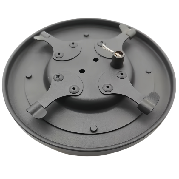
The Steel Deep Drawn Round Cover with Mounting Clips is a shallow drawn shell whose mounting story happens entirely at the edge: formed-in clips that snap over a mating lip and hold the cover without a single fastener. The draw makes the shell; the clip-forming operations after it decide whether the cover clicks on, stays on under vibration, and comes off again on purpose instead of by accident. We produce these covers in carbon steel on our mechanical and hydraulic presses with the clip features formed in second operations on the drawn blank, and this page covers the mechanics of making a clip-mounted cover actually hold.
Forming clips into a drawn cover edge changes the edge you drew
The clips are cut and formed out of the cover’s own rim or skirt, which means the draw and the clip features are sequential operations on one piece of sheet, and the sequence matters in both directions. A clip tab blanked out of a drawn edge removes hoop continuity — the edge below each cut relaxes inward, and on a shallow steel shell that relaxation can pull the adjacent rim in by several tenths of a millimeter, enough to change the interference the clips were designed around. We form the draw, trim to the clip-development outline, blank the clip windows, and then form the clips in a die that also re-sizes the rim, so the finished rim diameter is manufactured after all the material-moving operations are done, not before.
The reverse interaction is worse: clips fully formed before a restrike or sizing operation get re-bent by everything downstream. Any operation that re-forms the shell after the clips exist has to locate off features the clips do not load, or it uses them as datums and bends them as a side effect. Our routings on this family draw first, trim and blank second, clip-form and size in one final station — the clips are the last geometry made, and nothing after them touches the part’s form.
Springback compensation on clip geometry
A formed clip is a cantilever, and steel springs back. When the forming punch retreats, the clip’s beam relaxes a few degrees toward its flat state — one to three degrees on SPCC in the 0.8 to 1.5 mm range for a simple bend, more for radius-heavy forms — and the clip’s effective interference against the mating lip drops with it. The die does not cut the angle the drawing shows; it cuts the angle the material will hold after it relaxes. We establish the compensation on tryout parts: form, measure the relaxed angle, adjust the die, repeat — typically two or three iterations before the clip lands at drawing angle in the free state.
Springback also varies with where the material came from. Clip material cut from a region of the drawn shell that work-hardened during the draw springs back more than material from a low-strain zone — the same die, fed clips from different rim positions, produces different relaxed angles. On round covers that is actually manageable: the strain is axisymmetric, so every clip sees the same history, and one compensation serves all. The moment a cover design puts clips asymmetrically relative to a formed feature, we re-bracket the compensation per clip location, and the tool gets individualized forming punches instead of one shared angle. We surface that difference at review because it is the difference between a tool that tunes once and a tool that tunes every time the material lot changes.
Retention force targets for clip-mounted round covers
A cover that mounts on clips lives or dies by numbers nobody prints on the drawing: the push-off force that removes the cover, and the rattle threshold below which vibration makes it sing. Our practice on this family is to establish both at first article with the customer’s actual mating part or a gauge replica of it, and to write the agreed values into the acceptance criteria. As working rules: a small appliance-class round cover wants on the order of 15 to 30 N of push-off per engagement point to stay put under handling and modest vibration, and a cover that must survive transport vibration or a defined shake profile gets its retention set from the profile, not from habit.
Retention is manufactured from three levers in the die: the clip’s deflection length (longer beam, softer engagement, lower force), the interference depth at the mating lip (deeper engagement, higher force, and past a threshold, permanent set on removal), and the back-angle of the clip’s catch face (a shallow angle releases under lower force and feels forgiving; a steeper angle locks and resists removal the customer might actually want). The levers trade against assembly ergonomics — a cover that needs 60 N and a screwdriver to remove is a design decision, not an accident, and it should be made deliberately in the die design rather than discovered at the assembly line. We test engagement force on the push-off fixture both ways: install force and removal force, because a cover that installs at 80 N is its own field problem.
Draw depth, clip engagement and the interference that holds
The clips grip a mating lip, and the geometry that makes the grip work is a stack of tolerances from three features: the drawn rim diameter, the clip free-state diameter, and the mating part’s lip. The interference is the difference between the clip’s unconstrained diameter and the lip it snaps over, and on this family we target a working interference of 0.3 to 0.8 mm per engagement — below that range the cover falls off in shipment, above it the clips take permanent set on the first removal and never recover. The drawn rim carries the +/-0.1 mm as-drawn class, the clip forming holds its own angle and radius within the die’s compensation, and the engagement arithmetic has to survive all of it stacked worst-case, which is why we measure clip free-state diameter on the tryout parts and again on first article before the tool is accepted.
Draw depth sets how much skirt there is to form clips from. A shallow cover with a short skirt leaves the clip beam little length to deflect, forcing a stiff, high-force engagement; a deeper skirt gives the beam room to flex and the cover a gentler snap-on, at the cost of a deeper draw on the shell. Where a customer’s shallow-draw cover wants light engagement forces, the honest fix is often clip geometry — tapered lead-ins, localized relief cuts at the clip roots that lengthen the effective beam — rather than asking the draw for depth it does not need. Those relief cuts are blanked with the clip windows and sized in the same tryout loop, so the final geometry carries the field-proven numbers, not the first guess.
How we verify clip retention on round covers
Verification on this family is built around the engagement, because that is what the part is:
- Push-off force per clip and for the full cover, measured on a force gauge fixture with the cover seated on the drawing-specified mating gauge, in both the installation and removal directions — the values compared against the acceptance targets set at first article.
- Clip free-state diameter on sampled parts, checked before assembly into the fixture, so a drift in springback compensation shows up as a diameter trend before it shows up as a retention failure.
- Drawn rim diameter and profile, gauged at the clip planes and between them, against the as-drawn tolerance class the engagement arithmetic assumed.
- Engagement and disengagement cycling on sampled parts — typically twenty install-remove cycles — with the push-off force re-measured after cycling to confirm the clips are not taking progressive permanent set in normal service.
- Clip window edge condition: burr direction and height on the blanked windows, since a burr on the clip’s working face scrapes the mating lip every cycle and is a noise-and-wear mechanism hiding in plain sight.
- Shell form and surface verification per the drawing’s callouts, after all forming is complete — last, deliberately, so the checks run on the part as it ships.
The fixture and the acceptance values belong to the part number and are archived with the first article, so a lot measured this year is measured against the same engagement standard the tool was accepted on — not against whatever gauge happened to be free that afternoon.
Sizing the draw for a part like this — reduction per station, ironing allowance, flange width — is covered step by step in our deep drawn covers guide.
Specifications
| Item | Steel Deep Drawn Round Cover with Mounting Clips |
|---|---|
| Brand | AUNOV |
| Designing | A drawing file or a physical sample starts the review, the quotation comes back with a manufacturability review attached. |
| Tooling | Tooling designed and cut in house, each die held against your part number. |
| Samples | First articles go out with dimensional data and material certs. |
| Materials | Carbon steel (SPCC / DC01) leads the stock list for this part, alongside 304 / 316 stainless steel, aluminium, brass and copper, per the drawing. |
| Surface finish | Finish options: plating, e-coat, powder coating, anodising or passivation, fixed at the drawing review. |
| Processing | Multi-stage drawing, annealed in line where wall thinning calls for it, pierced and machined on the same floor. |
| Equipment | 5-250 T mechanical presses plus 250-500 T hydraulic presses, CNC turning and milling cells, a climate-controlled CMM room. |
| Tolerance | Drawn tolerances held to +/-0.1 mm, machined features held to +/-0.03 mm. |
| Delivery terms | Prices FOB, with DDP for EU and US on request, payment T/T or L/C, D/P for repeat accounts, blanket orders and call-offs supported. |
Related Products


Request a Quote for This Part
Send a drawing or sketch — get material advice, tooling cost and a per-piece price within 24 hours (working days).