
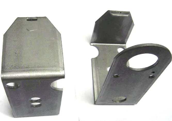
Mould and press forming is a tooling problem, and the tool is the product
Deep drawn, stamped, mould-press formed parts – this is a tooling and forming description rather than a part description, and it describes the class of work where the customer’s drawing is realised in a tool that becomes a lasting asset. In this family the difference between a good part and a bad one is rarely the stamping; it is whether the tool was designed for the part or adapted to it, and whether the tool’s maintenance is a scheduled part of production or a response to a problem.
We progressive die stamp these, trimmed and formed in one pass, and first articles verify the whole flow before the run is released, on a press shop with 5-250 T mechanical presses and dedicated dies, backed by CNC turning centres and a climate-controlled inspection room. Formed features to +/-0.05 mm and overall length to +/-0.1 mm, and critical dimensions carry CMM data with the shipment. Materials held include carbon steel, 304 and 316 stainless steel, aluminium and brass, with grade and temper confirmed in writing before tooling. Plating, coating or polishing to suit the drawing, with masking and laser marking available where needed. This page is about tool design, tool ownership, and the four questions that decide whether a customer’s tooling becomes an asset or a liability.
Tool design: made for the part, not adapted to it
Most tooling problems are design problems that were never resolved and were absorbed by the tool. A tool designed for the part makes several decisions deliberately; a tool adapted to the part makes them by compromise. The differences are visible in the finished part:
- Relief and the undercut question. A formed feature with an undercut cannot be ejected from a die by a simple punch, and the tool has to be designed with a relief, a loose piece, or a side core. A tool that was adapted will have a compromise here, and the compromise shows up as either a restricted feature or a tooling modification cost later.
- Material flow and the corner radii. A tool designed for the material has punch and die radii sized to the sheet’s formability, and the part forms without thinning unevenly or cracking. A tool adapted to the part will have whatever radii the existing tooling has, and the material will be asked to cope with it. This is the most common cause of a part that forms but cracks at the shoulder.
- The piercing sequence. A well-designed progressive die pierces the holes early, in flat material, and forms later. A poorly sequenced one pierces in formed material, where position accuracy is worse and the punch sees a work-hardened surface. The part looks the same; the tooling life and the position accuracy are not.
- Blank size and the draw ratio. A tool designed for the part uses a blank and a sequence that keep the draw ratio within the material’s limits at every stage. A tool adapted to the part works with the blank it has, and the thinning is higher than the drawing assumed. This shows up in the wall thickness, which is why a wall held to print is a tool-design specification as much as a drawing one.
Tool ownership, and why it needs to be on the quotation
Tooling on a part like this is a significant asset, and its ownership is genuinely ambiguous in the industry. Four things that should be established at quotation rather than discovered later:
- Who owns the tool. Ownership determines who can maintain it, who can modify it, and what happens to the part’s supply if the relationship ends. This is a commercial question with real consequences and it belongs on the quotation, not in a conversation.
- Whether the tool is dedicated to this part or shared. A dedicated tool is an asset that stays with the part. A shared tool is a compromise that can be modified for another job, which means the part’s future supply is at risk whenever that happens.
- The tool’s expected life, and what happens at end of life – whether a replacement is quoted, at what cost, and on what lead time. On a part in production for years this is a supply-chain question as much as a tooling one.
- Maintenance responsibility and record-keeping. Which party maintains the tool, and whether the maintenance history is recorded against the part number. A tool with no recorded maintenance history is a tool whose condition nobody can predict, and that eventually shows up in a batch of out-of-tolerance parts.
Tool wear is a production-planning item, not a quality surprise
On a stamping, the tool wears and the part drifts. This is a normal, predictable phenomenon, and the only question is whether it is planned for. Four requirements that make it manageable:
- Know which dimensions are wear-sensitive. A pierced hole’s diameter, a formed feature’s height, a blank’s outline – these move as the tool wears. A dimension set by the die’s geometry but not by a cutting edge will not move. Knowing which is which tells you what to check and what to plan for.
- Set a tool-change interval, based on the wear-sensitive dimensions and the tolerance band available. A part with a wide band on every functional dimension can run a long time between changes; a part with a tight band on a pierced hole needs short intervals or a re-cut plan.
- Check in-process, not just at the end. In-process checks between stages catch a drifting tool on the batch rather than on the customer’s dock. On a part where the wear-sensitive dimension is a hole’s size, an in-process check is cheap and catches the problem in a few hundred parts instead of a few thousand.
- Keep the tool in a state where it can be recovered. A tool that is slightly worn can often be re-cut or shimmed; a tool that is damaged or has been modified destructively cannot. This is a maintenance philosophy question and it is worth agreeing it at the start.
Material, and the temper question that the tool depends on
Materials held include carbon steel, 304 and 316 stainless steel, aluminium and brass, with grade and temper confirmed in writing before tooling. On a tooled stamping this confirmation is not paperwork – the tool is designed around a material’s behaviour:
- The temper decides the springback, and springback decides the tool’s compensation. A tool designed for annealed mild steel and then used with a harder grade will produce a part out of angle, and the tool is not wrong – the material is different from what the tool was designed for.
- Stainless Steel work-hardens faster and is harder on the tool. A stainless steel tool wears several times faster than a mild steel one on the same geometry, and the tool life and the tonnage are different. A tool designed for steel and used for stainless steel is a common and expensive discovery.
- Aluminium is softer and gummier. It wears differently, it can pick up and transfer material onto the tool’s surface, and it needs a different lubricant and a different tool surface treatment. A tool designed for steel often needs modification for aluminium rather than just a change of lubricant.
- Brass and copper are relatively easy on a tool and cut cleanly, and they are a good case where a steel tool works without modification.
First articles, and what verifying the flow actually means
First articles verify the whole flow before the run is released. On a tooled stamping that means more than measuring the part – it means confirming that the process produces a conforming part consistently, and the three things worth checking are:
- The part, measured against the drawing’s functional dimensions rather than its general ones. A first article that measures everything and reports everything often fails to highlight the two dimensions that matter.
- The process, at both ends of the die’s capability. A first article from one part in the middle of the run tells you the tool is producing a conforming part now. It does not tell you what the tool produces at the end of its life. Where a wear-sensitive dimension is close to a limit, a capability study or a pair of articles over a simulated tool life is worth more than a single inspection.
- The features that the tool’s design decisions affect – the pierced holes’ positions, the formed features’ angles, the wall thickness at the shoulder. These are the ones where a tool-design compromise shows up, and they are worth a specific look.
Design changes are what make tooling expensive
Eight things, and the first three are the ones that make the tooling succeed rather than merely exist:
- Material grade and temper, confirmed in writing before tooling. On a tooled part this is a tool-design input, not a purchasing note.
- Which dimensions are wear-sensitive and which are not, where the customer has a view – because it determines the in-process check plan and the tool-change interval.
- Tool ownership, dedicated versus shared, and the tool’s expected life, stated on the quotation.
- Formed features at the tight band, with the functional dimensions flagged and the rest left general.
- Overall length and the blank outline, and whether they are set by the die’s geometry or by a cutting edge – which is what determines whether they will drift.
- Any feature with an undercut or a side feature, called out for the tool-design review, because it determines the tool’s architecture.
- Wall thickness, held to print, with the minimum location, because the wall is a consequence of the tool’s blank and sequence.
- Finishing, with masked areas, and whether dimensions apply before or after finish.
How long in production, and how many design changes?
Direct answer: A dedicated tool is a large up-front investment and it is a good investment for a part in production for years with a stable design. For a part that will be revised twice, the second revision’s tooling cost is the argument against it – and on a part with a short life, a simpler tool or a slower process that is cheaper to change can be the better answer. It is worth having that conversation at enquiry, because the answer changes the tooling line in the quotation and it is much cheaper to have it before the die is cut than after the first revision arrives.
Who owns the tooling on a stamped part, and why does it matter?
Direct answer: It is genuinely ambiguous in the industry and it should be settled at quotation. Ownership determines who can maintain the tool, who can modify it, and what happens to the part’s supply if the relationship ends. It is a commercial question with real consequences, and it belongs on the quotation rather than being discovered later.
Why does a stamped part drift as the tool wears?
Direct answer: Because the tool wears and the part moves with it – a pierced hole’s diameter, a formed feature’s height and a blank’s outline all drift as the cutting edges and the die wear. This is a normal, predictable phenomenon, and the only question is whether it is planned for. Knowing which dimensions are wear-sensitive, and agreeing the tool-change interval against them, is what turns tool wear from a quality surprise into a production-planning item.
This part belongs to our Custom Metal Stamping Parts range. The custom metal stamping parts pages collect the process notes, common materials and inspection points behind every product in the family.
Specifications
| Item | Galvanized Stamped Brackets with Circular Cutouts |
|---|---|
| Brand | AUNOV |
| Designing | Send drawings, or send a sample to be measured – DFM notes are returned before any tooling is cut; the approved drawing is kept as the controlled master. |
| Tooling | Progressive and drawing dies are designed and built in house, so a die can be re-cut against the approved drawing, and first-article timing is measured from the tooling start date. |
| Samples | Sample and first article are the same discipline here: measured, reported, then approved. |
| Materials | Materials held include carbon steel, 304 / 316 stainless steel, aluminium and brass; grade and temper are confirmed in writing before tooling. |
| Surface finish | Plating, coating or polishing to suit the drawing; masking and laser marking available where needed. |
| Processing | Progressive die stamping, trimmed and formed in one pass; first articles verify the whole flow before the run is released. |
| Equipment | Press shop with 5-250 T mechanical presses and dedicated dies, backed by CNC turning centres and a climate-controlled inspection room. |
| Tolerance | +/-0.05 mm on formed features, +/-0.1 mm on overall length; critical dimensions carry CMM data with the shipment. |
| Delivery terms | CIF or DDP, with FOB available, T/T with deposit and L/C for larger runs; each volume tier carries its own quoted price. |
Related Products


Request a Quote for This Part
Send a drawing or sketch — get material advice, tooling cost and a per-piece price within 24 hours (working days).