
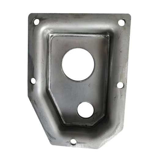
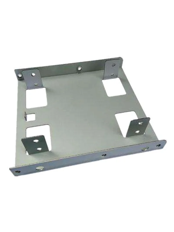
A bent and deep-drawn hardware part in two materials is a small assembly that most people specify as if it were one solid piece. The moment it is made from aluminium and stainless steel together, it becomes a dissimilar-metal assembly with its own failure modes — thermal mismatch, galvanic corrosion, differential wear — and every one of those is a design decision rather than a manufacturing detail.
The part that makes this interesting is that the two materials arrive at the same task by different routes. One is bent, one is drawn. One is machined, one is not. The specification has to carry two process descriptions and a joint between them, and the joint is where the engineering actually is.
Bending and drawing are different contracts
A bend says: the material stays at its full thickness, and the part is longer around the outside of the bend than the inside. A draw says: the material thins, and the wall distribution follows the shape. On a part where one section is bent and another is drawn, the wall around the whole part is not uniform, and the drawing has to reflect that rather than stating one thickness.
- In the bent region, the wall is the material thickness, unchanged. The consequences are that a hole near the bend changes shape when it is formed, that the effective radius at the bend controls a crack initiation point, and that the bend is where the surface will show a forming mark if the tooling is not finished properly.
- In the drawn region, the wall varies, thinning at the corners. A fastener through a drawn wall has to tolerate a variable bearing surface.
- Across the transition, the strain state changes discontinuously. This is where a crack appears if the transition is sharp.
So a single nominal wall on a combined part is a nominal that is wrong in at least two places. The drawing needs the wall at the bent section, the wall range at the drawn section, and a minimum at the transition.
Bend allowance is not a constant, and aluminium disagrees with the table
Every bending calculation reduces to the question of how much material goes into forming the bend rather than staying flat. Two variables dominate: the bend radius as a multiple of thickness, and the material’s yield-to-tensile ratio.
The yield-to-tensile ratio is the one that catches people. Mild steel and most stainless steel grades have a relatively narrow yield-to-tensile spread, so the bend allowance is predictable. Aluminium alloys — particularly the 5000 and 6000 series — have a much lower yield-to-tensile ratio, which means:
- The bend springs back substantially more.
- The bend allowance is more sensitive to the exact alloy and temper, so a generic table is unreliable.
- A larger bend radius is needed to avoid cracking, particularly in the harder tempers.
- The springback must be compensated in the tooling, and the compensation is a number that has to be developed rather than read off a chart.
For a small precision part this matters more than it sounds. A bend allowance that is 0.3mm out produces a hole that misses its mating part by 0.3mm, and at this size that is a scrap rate problem.
The joint between two metals
This is where dissimilar-metal assemblies fail, and the failure is not usually at the joint itself. It is next to the joint, in the weaker material, at the point where the stress concentrates.
Consider the mechanical options:
- Riveted. Permanent, strong, and it leaves a crevice under the head. On an aluminium part with a stainless steel rivet that crevice holds moisture and becomes a galvanic cell. Also, a rivet hole in a thin drawn wall deforms the wall.
- Threaded and screwed. Serviceable and it needs a thread that does not gall — a stainless steel threaded insert in an aluminium part is the standard solution. The insert is a separate part with its own specification.
- Adhesive bonded. No crevice, good load distribution in shear, poor in peel. The surface preparation of aluminium is the critical step and it is not a formality.
- Welded or brazed. The strongest joint, and the one that creates the most problems. Welding aluminium to stainless steel requires a dissimilar filler, produces a brittle intermetallic layer if the process is wrong, and needs the aluminium’s oxide layer to be removed immediately before welding.
- Overlapping formed features. A rolled edge or a hem on one part engaging a feature on the other. No third material involved and no crevice, and it is serviceable. Frequently the best answer for a small assembly.
Whatever the method, the drawing has to specify the joint, because the joint determines whether the part is assembled or welded, whether it can be serviced, and what the failure mode will be.
Galvanic corrosion and crevices
Aluminium and stainless steel in contact with moisture produce a galvanic cell in which the aluminium is the anode and corrodes preferentially. The severity depends on the area ratio: a small aluminium surface coupled to a large stainless steel surface is a severe case, because the small area carries the whole current.
The practical mitigations, in the order they should be considered:
- Eliminate the moisture path. Seal the joint so electrolyte cannot enter. This is the best answer and it is often achievable.
- Eliminate the contact. A polymer washer, sleeve or coating between the metals.
- Coat the stainless steel. A plating or passivation layer reduces the stainless steel’s electrode potential difference, though it does not eliminate the couple.
- Anodise the aluminium. A hard anodised layer is a good barrier, but the anodising also changes the dimensions and has to be specified with that in mind.
- Design the aluminium as the sacrificial element, so that if corrosion does occur, the part that is easier to replace is the one that loses metal.
On a drawing, the relevant specification is which surfaces are in contact and which are sealed, and this is one of those items that is cheap to state and expensive to discover.
Differential wear is the failure nobody plans for
Where the two materials move against each other — a sliding joint, a rotating fastener, a clamping face — the harder material will cut into the softer one, and the rate depends on the pair and on whether a lubricant is present.
Aluminium against stainless steel is a poor bearing pair in the absence of a hard treatment on the aluminium, because the aluminium gouges and then work-hardens into a hard surface that then abrades the stainless steel. Anodising the aluminium hardens its surface and transforms the wear behaviour, which is why hard anodise is common on aluminium hardware that bolts to a stainless steel frame.
If the joint slides, the drawing should call out the surface finish of both faces and, where it matters, a lubricant or a dry-film treatment.
Flatness and warpage on a mixed part
A part with a bent section and a drawn section has two different residual stress states joined together. The bent region has bending residual stress and a tendency to spring; the drawn region has drawing residual stress in a different direction. The assembled part will therefore distort, and the distortion is not a manufacturing variation — it is inherent to the combination.
Three ways to manage it:
- Restrain and release. A fixture that holds the part flat through the final operation leaves residual stress that relaxes later, so this defers the problem rather than solving it.
- Age naturally. Allowing the part to relax at ambient before final measurement, or a mild thermal treatment, gives a part that is stable afterwards. This is common on aluminium and is very effective.
- Design the bend radii generously. A tighter bend leaves more residual stress. A generous radius reduces both the stress and the springback, and on a precision part this is often the cheapest way to improve flatness.
Whichever is used, the drawing’s flatness tolerance should be verified after a defined settling period rather than immediately after the last operation.
Inspection that accounts for two materials
- Joint verification, not just dimensional. On a bonded joint this may mean a shear or peel sample; on a mechanical joint it means the fastener torque specification.
- Corrosion-relevant inspection. Is the sealant or coating actually present at every joint? This is verified visually on a sectioned sample and is the item most often omitted.
- Wall thickness at the drawn section, including the corners and the transition to the bent section.
- Bend angle and radius on the bent section, measured against the developed-length expectation rather than as a local radius.
- Flatness after settling, by the stated method.
- Surface finish on any sliding or bearing face, and on the anodised or coated surface where one is specified.
Questions worth asking on a mixed-metal hardware drawing
- Is each region labelled with its material, alloy and temper, rather than as a single part material?
- Is the wall specified separately for the bent section, the drawn section and the transition?
- Are the bend radii dimensioned, and is the alloy-specific springback allowance rather than a generic table value?
- What is the joint method, and is it specified as a requirement with its own acceptance criteria?
- Which surfaces are in contact, which are sealed, and is the galvanic arrangement acceptable at that area ratio?
- Where there is sliding or bearing contact, is the surface finish of both faces specified?
- Is flatness measured after a defined settling period?
- Is the dimensional inspection staged, so a bend error is caught before the joint is made?
The last question follows the same pattern that applies to every combined process in this group. When two processes are combined — bending and drawing, drawing and machining, forming and hydroforming — the inspection has to be staged at the boundary, otherwise a forming error is discovered only after the irreversible second operation has been performed on it.
This part belongs to our Custom Metal Stamping Parts range. The custom metal stamping parts pages collect the process notes, common materials and inspection points behind every product in the family.
Specifications
| Item | Bent and Deep-Drawn Metal Hardware Parts |
|---|---|
| Brand | AUNOV |
| Designing | Send drawings, or send a sample to be measured – samples are reverse-measured into a controlled drawing; revisions are re-quoted once rather than silently absorbed. |
| Tooling | Tooling is built and held under your part number, so tooling lead time stays under our control, and maintenance is tracked against the part number. |
| Samples | Sample parts are measured and reported before submission, so the sample is retained as the master, and later batches are gauged back to the signed sample. |
| Materials | Carbon steel, 304 / 316 stainless steel, aluminium and brass are all held in stock; special grades are sourced to the drawing when volumes justify. |
| Surface finish | Natural, plated or coated – the print decides, and the agreed finish is logged; masking and laser marking available where needed. |
| Processing | Stamping and forming in a progressive die with minimal secondary work; batch records are filed so a repeat order starts from approved data. |
| Equipment | Mechanical presses 5-250 T, in-press forming and piercing; secondary ops run on CNC turning centres, inspection on the CMM. |
| Tolerance | +/-0.03 mm on pierced holes, +/-0.1 mm on formed sections; critical dimensions carry CMM data with the shipment. |
| Delivery terms | FOB Ningbo or Shanghai, payment by T/T, L/C at sight or D/P; each volume tier carries its own quoted price. |
Related Products
Request a Quote for This Part
Send a drawing or sketch — get material advice, tooling cost and a per-piece price within 24 hours (working days).