
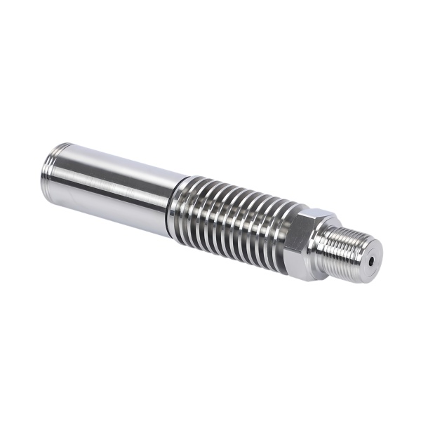
The probe shaft’s straightness over its free length is the difference between insertion and jamming
A threaded probe shaft—the long slender body of a temperature or pressure probe that threads into a process at one end—must enter a bore or thermowell that often clears it by only 0.1–0.3 mm. Over a 300 mm length, a bow of 0.2 mm (entirely possible after machining stresses relax) means the tip contacts the well wall, and the operator forces the probe “home” with the threaded fitting, springing the shaft and scraping the well.
We machine probe shafts with a strategy dedicated to straightness: rough turn with stock left, stress-relieve (300 °C, 2 hours for austenitic stainless steel), then finish turn in light passes. After machining, every shaft is checked for bow on a surface table: the shaft is rolled on a flat and the peak-to-valley indicator reading is recorded. Acceptance is a bow under 0.1 mm per 300 mm for standard probes, and under 0.05 mm for tight-clearance thermowell probes. Shafts exceeding the limit are straightened (press straightening with indicator feedback, never hammer) and re-checked—straightening adds a little residual stress, so we limit it to one cycle before scrap.
Tip geometry determines both thermal response and mechanical survivability
The probe’s tip—the closed end that faces the process—carries competing requirements. A thin, pointed tip responds fast (less thermal mass between the fluid and the sensing element); a rounded or hemispherical tip resists impact and erosion from the flowing fluid and survives insertion into wells without gouging.
Our standard tip for general industrial probes is a 60° truncated cone with a small flat (0.5–1 mm) at the apex. For fast-response probes, the tip is reduced in wall thickness (0.5 mm at the dome) with the sensing element potted directly against it; this halves the response time but reduces tip pressure rating, so the drawing must state which requirement leads. For abrasive-fluid probes (slurries, catalyst lines), the tip is left full-thickness and domed—response suffers, but the probe survives.
Thread-to-body concentricity keeps the probe centered in its well
If the threaded fitting end of the probe shaft is eccentric to the probe body, the probe threads into the process cocked: one side of the shaft’s length lies against the well wall even when the shaft itself is straight. The consequences are slower response (the shaft is touching the wall on one side, insulating the other side from flow), asymmetric wear, and on spring-loaded assemblies, a sideways load that fatigues the shaft over thermal cycles.
We machine the fitting thread, the body diameter, and the tip all in one setup (between centers or in a collet indexed to a single datum), holding thread-to-body concentricity at 0.02 mm TIR. Shafts that get second-operation machining (cross holes for mounting, a milled flat for a connector key) are re-indicated on their original datum—never re-chucked on an arbitrary surface—so the concentricity built in the first setup is preserved.
Cross-hole and flat features on slender shafts create stress risers that matter under vibration
Many probe shafts carry secondary features: a cross-drilled hole for a retaining pin, a milled flat for anti-rotation, or a thread relief groove. On a slender shaft under vibration (probes in pumps, compressors, and engines vibrate at the machinery’s frequency), each feature is a fatigue initiation site if its geometry is wrong.
The rules we machine to: cross holes get fully rounded exits (ball-nose-deburred to R0.3 minimum; a staked burr at a hole edge is a crack starter), milled flats get a filleted blend into the shaft OD (R0.5 minimum, never a sharp step), and thread reliefs at diameter changes get a radius of at least 0.25× the smaller diameter. These details cost seconds of cycle time; skipping them costs field failures that always look mysterious (“the probe just snapped at the flat”) because the stress analysis never models the burr.
How we verify a threaded probe shaft before shipping
- Straightness: Surface-table roll check on 100 % of shafts; bow recorded on the inspection report.
- Concentricity: Shaft on V-blocks at the fitting end’s thread pitch diameter; indicator on the body OD and at the tip. Acceptance: 0.02 mm TIR.
- Threads: Go/no-go per class; fitting thread engagement into a master port verified on first article.
- Tip: Profile check against the drawing’s tip geometry (optical comparator on first article; visual on every part for dings or closure of the dome).
- Wall thickness at the tip (for reduced-tip designs): Ultrasonic or sectioned sample on the first article; tip pressure rating confirmed by a burst test on one shaft per design change.
- Response test (if specified): One assembled probe per batch into a 60 °C water bath; one time constant recorded against the drawing’s requirement.
This part sits inside our CNC Machining Parts range. Across the cnc machining parts pages you will find the process notes, common materials and inspection points behind every product in the family.
Probe tip protection in shipping and insertion
A threaded probe shaft ends in a tip that is often the sensing surface, and that tip is the part most likely to be damaged before it ever reads anything. We cap or sleeve the tip for shipment and we design the tip so insertion does not score it against the well wall, because a damaged tip reads wrong and blames the process, not the handling. The protection is part of the part, not just the box, so the probe arrives capable of the accuracy the certificate claims. We flag the tip as the fragile end on the drawing so nobody treats the shaft like a plain rod.
Recalibration interval and what drifts first
A probe drifts, and the question is which characteristic moves first so the interval can be set honestly. We qualify the shaft for stability and we state a recalibration period tied to the use, because a probe left in service past its drift window quietly biases every reading it takes. The interval comes from testing, not from a default, and we share the drift data with the buyer so the schedule is defensible. A probe program without an interval is a measurement program on faith.
Specifications
| Item | Stainless Steel CNC Machined Threaded Probe Shaft |
|---|---|
| Brand | AUNOV |
| Designing | A drawing file or a physical sample starts the review, you get a DFM review together with the quotation. |
| Tooling | Our own toolroom designs and builds every die, held under your part number. |
| Samples | The first-article set ships with dimensional data and material certs. |
| Materials | 304 / 316 stainless steel is the primary stock for this part, alongside carbon steel (SPCC / DC01), aluminium, brass and copper, and the grade is fixed at the drawing review. |
| Surface finish | Surface treatment per the drawing: plating, e-coat, powder coating, anodising, passivation, per your print. |
| Processing | Staged deep drawing, with in-line annealing where the draw ratio requires, pierced and finish-machined on the same floor. |
| Equipment | Press capacity spans 5 to 500 T across mechanical and hydraulic lines, with CNC turning and milling cells and a climate-controlled CMM room. |
| Tolerance | Tolerances to +/-0.1 mm as drawn, +/-0.03 mm on machined features. |
| Delivery terms | Prices FOB, with DDP for EU and US on request, T/T or L/C, D/P on repeat business, call-off schedules supported. |
Related Products


Request a Quote for This Part
Send a drawing or sketch — get material advice, tooling cost and a per-piece price within 24 hours (working days).