
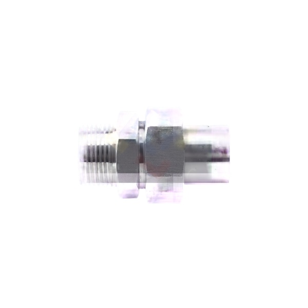
A threaded coupling must hold two shafts collinear within a few hundredths of a millimeter
A threaded coupling in shaft service—two threaded shaft ends joined by an internally threaded sleeve—must keep the two shaft axes collinear. The error sources stack: each thread’s clearance fit allows a small tilt, and any thread eccentricity adds offset. A clearance-fit thread pair (class 2A/2B) on a 16 mm shaft can allow up to 0.5° of tilt per connection; over a 100 mm coupling, 0.5° is 0.9 mm of runout at the far shaft end.
Where shaft alignment matters, we machine couplings with a piloted register: a bored pilot at each end of the coupling (a smooth cylindrical land slightly larger than the thread) that fits the shaft’s unthreaded land with H7/g6 clearance. The threads pull the joint together; the pilots carry the alignment. Thread run-out then stops mattering, because the pilot—not the thread—defines the axis. Couplings for instrument spindles and lead screws are essentially always piloted; plumbing-style couplings (where the “shafts” are just pipes) need only thread quality.
Torque transmission through the threads sets the engagement length
When a threaded coupling transmits torque (not just holds pipes), the torque shears the engaged threads. The engagement length must be calculated, not guessed: L = 2T / (π d² p τ K / pitch terms), simplified in practice to the rule that steel-into-steel threaded couplings need engagement of at least 1.0 × nominal diameter for full strength, and 1.5× where the coupling’s internal thread is in a softer material than the shaft.
We machine the internal threads in the coupling to full depth (1.25–1.5× D) with a thread runout groove at each end so the last engaged thread is a full thread, not a partial one. A partial last thread concentrates the entire load’s tail on a fraction of its flank and strips first. The runout groove diameter is kept just above the thread major diameter so the groove doesn’t weaken the coupling wall.
Internal thread concentricity to the coupling OD can’t be gauged with a ring gauge
External threads gauge easily with ring gauges; internal threads are gauged with plug gauges, which verify fit but not position. The internal thread’s concentricity to the coupling’s OD must be measured another way—on a threaded arbor or by CMM probing the thread’s pitch cylinder.
Our method: machine the coupling’s OD, bores, and internal threads in one setup (part gripped on OD in a collet, internal thread single-point cut, then faced and chamfered), which builds concentricity into the process rather than inspecting it in afterwards. Verification on the first article and every 50th part: the part screws onto a threaded precision arbor, and an indicator run on the OD shows total runout—acceptance 0.03 mm TIR for standard couplings, 0.015 mm for piloted instrument couplings.
Thin-wall coupling nuts: balancing wrenchability against burst strength
A coupling’s wall around its internal thread must contain the spreading force that torque generates. A rule of thumb: the coupling’s OD should be at least 1.6× the thread’s nominal diameter for full-strength joints (matching standard coupling hex dimensions). Compact designs (OD 1.3–1.4× D) trade burst margin for envelope, which can be acceptable in low-torque instrument service but is dangerous in power transmission.
We check every custom coupling design with a simple hoop-stress calculation across the engaged thread’s minor diameter at the design torque, and flag any design where the calculated wall stress exceeds 1/3 of yield. In one recent case, a customer’s compact coupling (OD 1.35× D) for a 90 N·m service showed a calculated wall stress at 65 % of yield—we recommended returning to a standard 1.6× hex coupling, and the customer’s subsequent fatigue failure on a 1.4× prototype confirmed the call.
How we verify threaded couplings before shipping
- Internal threads: Go/no-go plug gauges per class on 100 % of parts; pitch diameter on every 25th with internal thread micrometers.
- Concentricity: Threaded-arbor runout check on OD (and on pilot bores for piloted designs): 0.03 mm TIR standard, 0.015 mm precision.
- Pilot bores (if designed): Air gauge or ball micrometer; size and roundness within H7.
- End faces: Face runout on the arbor, 0.02 mm; the faces clamp against the shaft shoulders on piloted designs and must be square to carry the clamp load evenly.
- Torque test (sample for power couplings): One coupling per batch assembled to master shafts and torqued to 1.5× rated torque; no slip, no thread elongation measurable (arbor re-check after test). For high-cycle applications, a 10,000-cycle torque reversal test on one part per design validates the thread’s fatigue margin.
CNC Machining Parts is the parent range for parts like this one; the overview page gathers the tooling logic, finishing options and tolerance notes that apply across the family.
Left-hand versus right-hand: avoiding a cross-threaded shipment
A threaded coupling looks symmetric until the thread direction matters, and a batch where some are left-hand and some right-hand is a field hazard if they are not marked. We tag the hand of every non-standard coupling on the part and on the pack, and we keep the two on separate fixtures so a setup error cannot slip one into the other lot. The cost of the marking is nothing next to a line that threads a right-hand shaft into a left-hand coupling and wrecks both. We treat hand as a specification, not an afterthought, on any coupling where it is not the default.
Anti-rotation when the coupling must not back off
A coupling that transmits torque also tends to unscrew itself unless something stops it, so we build in a flat, a pin hole, or a lock feature wherever the duty is vibratory. The feature is placed so it engages without weakening the thin wall at the thread relief, because that is the section already under the most stress. We size the locking feature to the torque it must resist, not to a catalogue default, and we verify it on a torque-to-failure sample because a coupling that backs off in service is a rotating hazard, not a nuisance.
Specifications
| Item | Stainless Steel CNC Machined Threaded Coupling |
|---|---|
| Brand | AUNOV |
| Designing | A drawing file or a physical sample starts the review, our engineers reply with a manufacturability assessment and pricing. |
| Tooling | Our own toolroom designs and builds every die, held under your part number. |
| Samples | The first-article set ships with dimensional data and material certification. |
| Materials | 304 / 316 stainless steel is the primary stock for this part, alongside carbon steel (SPCC / DC01), aluminium, brass and copper, with grade selection confirmed at drawing review. |
| Surface finish | Zinc, nickel or chrome plating, e-coat, powder coat, anodising or passivation, per your print. |
| Processing | Progressive deep draw stages with in-line annealing as the draw ratio demands, pierced and machined on the same floor. |
| Equipment | Mechanical presses 5-250 T, hydraulic presses 250-500 T, CNC turning centres and a climate-controlled CMM room. |
| Tolerance | +/-0.1 mm on as-drawn surfaces and +/-0.03 mm on machined surfaces. |
| Delivery terms | FOB standard, DDP offered for EU and US, T/T and L/C accepted, D/P for established customers, scheduled call-offs welcome. |
Related Products


Request a Quote for This Part
Send a drawing or sketch — get material advice, tooling cost and a per-piece price within 24 hours (working days).