
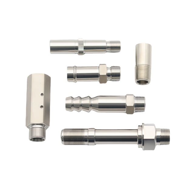
Thread form accuracy on a shaft determines whether the mating nut seats correctly or binds mid-thread
A CNC-machined threaded shaft—whether it carries a nut, a collar, a pulley, or a bearing locknut—depends on thread form accuracy for proper assembly. The most common defect is not incorrect pitch diameter (which is easily caught with a go/no-go ring gauge) but thread angle error: the included angle of the thread profile deviates from the nominal 60° (for metric) or 60° (for UN) because of tool wear, deflection, or incorrect grinding wheel dressing on single-point threaded shafts.
A thread angle error of 2–3° (easily produced by a worn threading insert that has developed edge build-up) causes the mating nut to contact only at the crest or root of the thread rather than along the full flank. The result is reduced load-carrying capacity (the effective contact area drops by 40–50 %), increased risk of galling under high preload (because the contact stress is concentrated on a small area), and difficulty in torque control—the nut feels tight at a lower-than-specified torque because the friction coefficient is elevated by the poor contact pattern.
We cut threads on shafts using either a precision ground thread die (for M6 and smaller, where single-point threading is impractical due to tool deflection) or a single-point threading tool with a TiAlN-coated carbide insert for larger sizes. The insert is replaced after every 500 shafts or when the thread angle verification (measured with a thread pitch comparator on every 100th part) shows deviation exceeding 0.5° from nominal. This conservative replacement interval costs approximately 0.02 USD per shaft in tooling but eliminates thread-angle-related assembly issues entirely.
Shaft runout at the bearing journals is what causes vibration, not the overall straightness
When a shaft is supported by rolling-element bearings at two journal locations, the vibration amplitude at operating speed is determined primarily by the runout at those journals relative to the axis defined by the journals themselves—not by the shaft’s overall straightness as measured between centers. A shaft can be perfectly straight (less than 0.01 mm TIR over its full length) but still produce excessive vibration if one journal has 0.02 mm of local runout (out-of-roundness or lobing) caused by clamping distortion during the final grinding pass.
We grind bearing journals in a single setup with the shaft supported on dead centers (not on steady rests, which can introduce lobing if not adjusted correctly). The target runout at each journal is 0.005 mm TIR maximum, measured with a dial indicator rotating the shaft on the same centers used for grinding. After grinding, we verify roundness with a V-block and indicator rotation check (three-lobing shows up as a consistent 0.01–0.02 mm variation per revolution that does not correct when the shaft is rotated 180° in the V-block). Shafts exceeding 0.005 mm TIR are re-ground with reduced stock removal (0.01 mm) to correct the error without changing the nominal diameter.
The transition diameter between features is a stress concentrator under rotating bending
Every threaded shaft has at least one transition diameter: where the thread ends and the unthreaded shank begins, where the shank steps down to a smaller diameter for a seal land, or where a shoulder locates a bearing inner race. Each of these transitions is a stress concentrator under the rotating-bending loads that all shafts experience to some degree. The stress concentration factor (Kt) ranges from 1.5 (for a generous fillet radius R = 0.3× the diameter step) to 3.0 or higher (for a sharp corner or a small fillet R < 0.1× the step).
We specify a minimum fillet radius of 0.3× the diameter difference at all shaft transitions unless the mating component geometry prevents it. For example, a shaft stepping from 20 mm (bearing journal) to 16 mm (seal land) has a 4 mm step; the minimum fillet radius is 1.2 mm. If the bearing inner race chamfer only accommodates R0.5 mm, we work with the customer to either (a) increase the bearing race chamfer (most bearings offer an R1 or R1.5 option), (b) reduce the step height by increasing the seal land diameter, or (c) accept the higher Kt and specify a shot-peened fillet surface to improve fatigue strength by 20–30 % despite the stress concentration. Option (a) is our first choice because it has no cost or lead-time impact; option (c) adds about 0.05 USD per shaft for the peening operation.
Surface finish at the seal land affects both seal life and leakage rate
The seal land—the portion of the shaft where a lip seal, oil ring, or mechanical seal makes running contact—is arguably the most functionally critical surface on any rotating shaft. A surface that is too rough (Ra > 0.4 µm) accelerates seal lip wear and generates debris that scores the seal; a surface that is too smooth (Ra < 0.1 µm) cannot retain the lubricating film that the seal needs to run on, leading to dry friction and overheating. The optimal range for most elastomeric lip seals is Ra 0.2–0.4 µm with a crossed-lay pattern (the direction of the grinding marks should be roughly perpendicular to the shaft axis, not parallel).
We grind seal lands with a traverse-grinding pass using a 180-grit wheel at 25 m/s peripheral speed, producing a surface with Ra 0.25–0.35 µm and a visible cross-hatch pattern at roughly 30° to the shaft axis. After grinding, we inspect the surface at 20× magnification for grinding burns (showing as blue-brown discoloration) and for chatter marks (showing as regular waviness perpendicular to the grinding direction). Burns indicate excessive heat during grinding that may have tempered the surface (reducing fatigue strength); chatter indicates wheel imbalance or machine vibration that will produce a non-circular seal land. Either condition triggers a re-grind with adjusted parameters before the shaft proceeds to plating or shipping.
Plating thickness on threaded sections must be accounted for in the pre-plate thread dimensions
Many threaded shafts receive a protective plating: zinc, nickel, chrome, or black oxide. Plating builds up on all exposed surfaces including the thread flanks, reducing the effective pitch diameter by roughly twice the plating thickness (once on each flank). For a class 6g thread with a pitch diameter tolerance of roughly 0.05 mm on an M12 thread, a zinc plating thickness of 8 µm reduces the pitch diameter by 0.016 mm—about 30 % of the tolerance band. If the thread was machined at the low end of the 6g range before plating, the post-plate pitch diameter may fall below the minimum acceptable limit, and the mating nut will not start or will bind during engagement.
We machine threads to the middle-to-upper side of the 6g tolerance band (roughly +0.02 to +0.04 mm from nominal pitch diameter) when the shaft will be plated. This ensures that after plating, the thread remains within the 6g range (now shifted downward by 2× the plating thickness). For critical applications where the customer specifies the post-plate thread class explicitly, we calculate the required pre-plate dimension using the formula: PD_pre = PD_nominal + PD_tolerance_midpoint + 2 × plating_thickness. This calculation is documented on the process traveler and verified on the first article by measuring both pre-plate and post-plate pitch diameters with thread micrometers.
How we certify that a threaded shaft meets all functional requirements before shipment
Our final inspection protocol for threaded shafts includes:
- Thread verification: Go/no-go ring gauge (6g) on every shaft. Pitch diameter measurement with thread micrometer on SPC sample (every 20th shaft). Thread angle check with optical comparator on first article and after tool change.
- Dimensional inspection: CMM check of all diameters, lengths, fillet radii, and chamfers against the drawing. True position of threaded holes (if any) relative to the shaft axis.
- Surface finish: Ra measurement at bearing journals (target ≤ 0.4 µm), seal lands (target 0.2–0.4 µm), and threaded sections (target ≤ 1.6 µm). Stylus instrument with 0.8 mm cutoff.
- Runout and concentricity: Total indicated runout at each bearing journal and seal land, measured between centers. Target ≤ 0.005 mm TIR for journals, ≤ 0.01 mm TIR for seal lands.
- Plating/coating verification: Thickness measurement by eddy-current or XRF on plated parts. Salt spray test (ASTM B117) on one sample per batch for corrosion-resistant specifications.
- Functional test: For shafts that ship as part of an assembly, test-fit with the mating nut/bearing/pulley to confirm smooth engagement and proper torque-tension relationship.
This protocol takes approximately 8 minutes per shaft in total (most checks are rapid go/no-go operations) and produces a Certificate of Conformance that accompanies each shipment. Our external PPM for threaded shafts over the past 12 months is 180, with the top three escape modes being: minor thread damage in transit (corrected with a thread chaser at the customer’s receiving dock), plating thickness out-of-spec on the thread flanks (addressed by adjusting pre-plate offsets), and cosmetic blemishes on non-functional surfaces (accepted by most customers after photo documentation).
The CNC Machining Parts range is the parent for parts like this one; tooling logic, finishing options and tolerance notes for the whole family are gathered on its overview page.
Specifications
| Item | Stainless Steel CNC Machined Threaded Shafts |
|---|---|
| Brand | AUNOV |
| Designing | Send the drawing, or a shaft sample we can measure, the quotation comes back with a manufacturability review attached. |
| Tooling | Dies engineered and produced in our own toolroom, held and maintained under your part number. |
| Samples | First-article samples ship with a dimensional report plus material certs. |
| Materials | Stock for this part leads with 304 / 316 stainless steel, alongside carbon steel (SPCC / DC01), aluminium, brass and copper, and the grade is fixed at the drawing review. |
| Surface finish | Finish options: plating, e-coat, powder coating, anodising or passivation, selected against the drawing requirement. |
| Processing | Multi-stage drawing, annealed in line where wall thinning calls for it, then pierced and machined in house. |
| Equipment | Mechanical and hydraulic press lines cover 5-500 T; CNC turning and milling cells and a climate-controlled CMM room support them. |
| Tolerance | +/-0.1 mm on as-drawn features, with machined features to +/-0.03 mm. |
| Delivery terms | Prices FOB, with DDP for EU and US on request, T/T and L/C; D/P on repeat accounts, blanket orders and call-offs supported. |
Related Products



Request a Quote for This Part
Send a drawing or sketch — get material advice, tooling cost and a per-piece price within 24 hours (working days).