
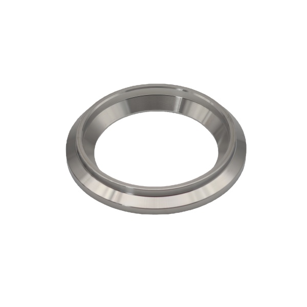
Seal ring cross-section shape determines the contact stress distribution against the mating surface
A precision-machined seal ring—whether it is a piston seal gland, a valve seat, a bearing isolator face, or a static sealing ring—generates its sealing pressure through the elastic deformation of its cross-section when compressed between the housing and the mating component. The shape of that cross-section (rectangular, X-profile, oval, D-shaped, or custom) determines how the contact stress is distributed across the sealing interface.
A rectangular cross-section (the simplest and most common) produces a roughly uniform contact stress when compressed to 20–30 % of its original height, assuming both mating surfaces are flat and parallel. An X-profile (with relief grooves on both faces) concentrates the contact stress at the inner and outer edges of the ring’s footprint, which improves sealing against low-pressure fluids but increases wear at the high-contact-stress points. A D-shaped profile (flat on one side, curved on the other) is used when one mating surface is rigid (a metal flange) and the other is compliant (a polymer or elastomer cover); the flat side seals against the metal, and the curved side conforms to the compliant surface without cutting into it.
We machine seal rings from 316 stainless steel, 17-4 PH, or bronze depending on the service conditions. The most demanding application for machining accuracy is the X-profile ring, where the relief groove depth must be held to ±0.02 mm because a groove that is too shallow does not relieve the center (contact stress remains uniform) and a groove that is too deep reduces the effective sealing area below what is needed to contain the system pressure.
Surface finish on the sealing faces must be optimized for the specific seal material
The surface finish of a seal ring’s sealing face interacts with the counter-face (the shaft, the housing bore, or the mating flange) in ways that depend on the type of seal being used. There is no single “best” finish—it depends on whether the seal is hard (metal-to-metal), soft (elastomer or polymer), or composite.
- Metal-to-metal seals (lapped faces, ground seats): Target Ra 0.1–0.2 µm with a circumferential lay (no cross-hatch). The surfaces must be flat within 0.001 mm per 25 mm diameter. Any deviation from flatness creates a leak path that high-pressure fluid will find. We achieve this by lapping after grinding, using a cast-iron lap plate with 1 µm diamond abrasive slurry.
- Elastomeric seals (O-rings, lip seals running against the ring): Target Ra 0.2–0.4 µm with a circumferential lay. Too smooth (Ra < 0.1 µm) and the seal cannot retain lubricating film → increased friction and heat. Too rough (Ra > 0.8 µm) and the seal abrasive-wears rapidly. Ground finish with a standard grinding wheel (180 grit) typically hits this range directly.
- Polymer seals (PTFE, PEEK, filled composites): Target Ra 0.4–0.8 µm. Polymer seals are harder than elastomers but softer than metals; they need enough roughness to “bite” into slightly for anti-rotation but not so much that they abrade. A standard machined finish with a carbide insert at recommended feed rate usually achieves this without extra processing.
Concentricity of the ID and OD determines whether the seal ring wears evenly or eccentrically
When a seal ring rotates relative to its housing (as in a rotating shaft seal) or when the shaft orbits within the ring (as in a misaligned bearing), the concentricity between the ring’s inner diameter (where it contacts the shaft) and outer diameter (where it contacts the housing) determines whether the wear is distributed uniformly around the circumference or concentrated on one side.
We hold ID-to-OD concentricity to 0.01 mm TIR for rotating seal rings and 0.02 mm TIR for static rings where slight eccentricity can be tolerated by the seal’s compliance. The verification method depends on the ring geometry: for thin-section rings (wall thickness < 3 mm), we measure on a CMM by probing the ID and OD at eight angular positions and calculating the center offset; for thick-section rings, we mount the ring on a mandrel and measure OD runout with a dial indicator while rotating. Rings exceeding the concentricity limit are re-chucked and given a light boring pass (0.03–0.05 mm stock removal) to correct the offset—this is possible only if sufficient grinding/machining stock remains; otherwise the ring is scrapped.
Flatness tolerance on the seal face must account for clamping distortion during assembly
A seal ring may measure perfectly flat on a granite surface plate (0.002 mm TIR) but warp by 0.01–0.03 mm when bolted into its housing due to uneven clamping force or non-parallel mating surfaces. This clamping-induced distortion is the single most common cause of seal leakage in field-assembled equipment—the ring was within spec when it left our factory, but the assembly process distorted it beyond its sealing capability.
We address this in two ways: first, we design the ring with sufficient stiffness (minimum thickness ≥ 5 % of the OD diameter for stainless steel rings under 10 MPa clamp pressure) so that clamping distortion stays below 0.005 mm even with worst-case torque variation (±20 % of nominal). Second, we include an assembly note with each shipment recommending a specific tightening sequence (star pattern, not clockwise sequential) and a maximum torque value that keeps the ring’s compressive stress below 30 % of yield. For customers who provide their own assembly instructions, we review those instructions against the ring’s stiffness calculation and flag any torque values that would cause excessive distortion.
Material selection for seal rings balances corrosion resistance, wear resistance, and galling tendency
The three most common materials for machined seal rings are 316 stainless steel, 17-4 PH precipitation-hardening stainless steel, and bronze (C93200 or C95400). Each has distinct advantages and limitations:
- 316 stainless steel: Best general-purpose choice. Excellent corrosion resistance in water, fuels, oils, and mild chemicals. Moderate wear resistance (can be improved by nitriding or applying a thin chrome plating). Tendency to gall (adhesive wear) when sliding against another stainless steel surface under load—requires lubrication or a dissimilar counter-face (bronze, hardened steel, or a coated surface).
- 17-4 PH (H900): Higher strength (HRC 38–43 vs. <95 HRB for annealed 316) allows thinner ring sections for the same pressure rating. Better wear resistance than 316 due to higher hardness. Same galling tendency as 316 (both are austenitic/martensitic stainless steels). Used when space is limited and the ring must also carry structural load.
- Bronze (Aluminum Bronze C95400): Excellent galling resistance against stainless steel shafts—this is why bronze bushings and thrust washers are standard in rotating equipment. Good corrosion resistance in seawater and many chemicals (better than 316 in sulfide-containing environments). Lower yield strength (~275 MPa for C95400) requires thicker sections than stainless steel for the same pressure rating. Used specifically for seal rings that must slide against a stainless steel shaft without lubrication.
For the “precision stainless steel seal ring” product category, the default is 316 unless the drawing specifies otherwise or the application involves dry running against another stainless steel component—in which case we recommend bronze or a coated stainless steel (chrome-plated or nitrided 17-4 PH).
How we certify that a seal ring batch meets the customer’s leakage specification before shipping
Every batch of seal rings undergoes a dimensional audit plus a functional seal test on a representative sample:
- 100 % dimensional inspection: OD, ID, width, concentricity (ID vs. OD), flatness of sealing faces, and surface finish. All measurements recorded. Parts outside any tolerance are segregated.
- Hardness verification: One sample per batch (or per heat-treatment lot) tested by Rockwell or Vickers microhardness. Confirms that heat treatment (if applicable) achieved the specified hardness range.
- Seal test (sample): One ring per 200 parts (minimum 1 per batch) is installed in a test fixture that simulates the actual assembly: the ring is clamped between the fixture halves at the specified torque, pressurized with the working fluid (or a surrogate fluid of matching viscosity) at 1.5× the design pressure for 30 minutes. Leakage rate is measured by collecting any fluid that passes the seal in a graduated container. Acceptance: zero visible leakage (< 0.01 cm³/min).
- Material certification: Mill certificate confirming alloy composition and heat treatment condition. For aerospace or medical applications, we also provide a full chemical analysis from an independent lab (ICP-OES) on one sample per melt.
This protocol has kept our external PPM for seal rings below 50 over the past 24 months, with the top two escape modes being minor flatness deviations (corrected by the customer re-lapping during assembly) and surface finish outliers (Ra 0.6–0.8 µm on parts that should have been 0.2–0.4 µm—addressed by adding an extra finishing pass to the process traveler).
CNC Machining Parts is the parent range for parts like this one; the overview page gathers the tooling logic, finishing options and tolerance notes that apply across the family.
Specifications
| Item | Precision CNC Machined Stainless Steel Seal Ring |
|---|---|
| Brand | AUNOV |
| Designing | Send us your 2D drawing, or mail a sample for measurement, our engineers reply with a manufacturability assessment and pricing. |
| Tooling | Dies engineered and produced in our own toolroom, with your part number on the tool record. |
| Samples | Sample parts arrive with a dimensional report plus material certs. |
| Materials | Stock for this part leads with 304 / 316 stainless steel, alongside carbon steel (SPCC / DC01), aluminium, brass and copper, with the final grade confirmed at the drawing review. |
| Surface finish | Zinc, nickel or chrome plating, e-coat, powder coat, anodising or passivation, per your print. |
| Processing | Staged deep drawing with in-line annealing where needed, then pierced and machined in house. |
| Equipment | Our press floor runs 5-250 T mechanical and 250-500 T hydraulic presses, in-house CNC cells and a temperature-controlled inspection room. |
| Tolerance | +/-0.1 mm as-drawn, +/-0.03 mm on machined surfaces. |
| Delivery terms | FOB standard, DDP offered for EU and US, T/T and L/C accepted, D/P for established customers, call-off scheduling supported. |
Related Products



Request a Quote for This Part
Send a drawing or sketch — get material advice, tooling cost and a per-piece price within 24 hours (working days).