
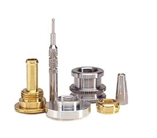
Milling is limited by tool reach and workholding, not by the machine’s nameplate
A CNC milling service is usually specified by axis count and by the machining envelope, and both are the least useful numbers. What determines whether a milled part is straightforward or difficult is whether a tool can physically reach every feature, and whether the part can be held rigidly enough while that tool is cutting. A part with a simple shape and a deep pocket in an awkward orientation is harder than a complex part that presents all of its features upward in one setup. This page is organised around those two constraints, because they are what actually shape the process plan.
On this work we run turn-mill machining with critical diameters finished in one setup, on 12 CNC turning centres with automatic bar feeders backed by CNC turning centres and a climate-controlled inspection room, with in-process checks between stages rather than only at the end. Ground faces are achievable to +/-0.005 mm where the print demands it, with GD&T per the drawing and PPAP-style reports on request. This is a service description, so the useful question is not “what can you make” but “what do I need to tell you so the answer is accurate”.
Reach: the first question about any milled feature
For every feature, three questions decide whether it is easy or difficult:
- Can a tool reach it, and at what stickout? A long slender cutter deflects. Deflection produces a feature that is out of position and out of size simultaneously, and it produces it worst at the deepest point. Deep pockets in a large cavity mean long tools and low feeds, and they are the single most common cause of a milling quote being higher than expected.
- What cutting ratio is available? A small cutter in a large open cavity has plenty of room. A small cutter in a narrow slot has almost none, and the tool will rub rather than cut on both walls. Narrow deep slots are among the hardest features in milling.
- How many directions does the tool have to approach? A feature reachable from one direction is one setup. A hole pattern that must be approached from both sides is two setups or a part that gets re-fixtured, and re-fixturing costs accuracy.
The design responses are all straightforward once you know they are available: open up a narrow slot into a pocket if the function allows, add a corner relief or a dogbone so a cutter can clear, avoid a through-hole in a wall that forces the tool to exit into a region it cannot reach, and orient the part so the majority of its features face the same way. None of these compromise a part functionally, and together they can move a milling operation from a difficult two-setup job into a simple one-setup job.
Workholding: where accuracy is actually decided
Every milling accuracy claim is really a workholding claim. A part that moves even a few hundredths under cutting force produces a feature that is out of position, and the machine’s accuracy is irrelevant at that point. On a milled part the practical measures are:
- Clamp on a surface that does not matter. Every part needs a clamping face, and on a milled part it should be designed in rather than improvised from a functional face.
- Clamp low and support close to the cut. A part supported only at one end deflects under a cutter at the other end. Support as near to the feature as practical reduces deflection more than a stiffer machine does.
- Use the part’s own features. On a milled plate or housing, locating on a machined dowel or on a tapped hole means the fixture and the part share a datum, and the fixture can never be set wrong relative to the drawing’s datum.
- Minimise the number of clampings. Fewer setups means fewer datum transfers, and this is the same principle that governs turning.
- Account for clamping force. A thin-walled part distorts under clamping and springs back when released. Where a wall is thin, either support it behind, or machine it unclamped using a vacuum or a low-disturbance method, or accept that flatness will not hold and specify the part on its machined datum.
Where tolerance is tight and the part is aluminium or a thin stainless steel wall, the honest answer is often that a fixture has to be made for the part, and that this is a tooling cost. Our toolroom covers die design, wire-cut EDM and maintenance, so tooling lead time stays under our control, and ownership is confirmed on the quotation – which matters because a dedicated fixture is an asset, not a consumable.
Turn-mill: one setup for a part that mixes both
Turn-mill machining – turning and milling in the same machine with the part held in one clamping – solves the setup problem for a specific family of parts: those that are round, or mostly round, and that have milled features on or near the axis. Critical diameters finished in one setup is the phrase worth noting, because it means the diameter and the feature that locates against it are related by the machine rather than by a fixture.
Where turn-mill is the right choice:
- The part is round and has flats, slots, cross-holes or keyways.
- A milled feature has to be square to a turned diameter – which is a common and important requirement.
- Part volume justifies programming a more complex machine rather than running two simple operations.
Where it is the wrong choice: a part that is fundamentally a plate or a prismatic block. On those, a genuine milling machine with a proper fixture is faster and cheaper, and forcing a prismatic part onto a turn-mill adds cost rather than removing it. Saying so is part of a useful review.
Where +/-0.005 mm comes from, and where it does not
Very tight milling tolerance is achievable on a ground surface, and the mechanism is worth stating plainly so the number is not misapplied. A ground surface is not produced by the milling operation – it is produced by a separate grinding step, or by a finishing operation that is functionally similar. So a drawing calling for +/-0.005 mm on a face is really calling for a grinding operation and its own setup, plus flatness and surface finish requirements, plus a handling route that does not damage the finished face.
Four consequences:
- Tight on size is not the same as tight on position. Grinding a face controls that face’s flatness and its size relative to the setup. It does not automatically locate that face’s position relative to a hole drilled earlier. Where position across a wide span matters, the feature has to be machined in one setup or the tolerance stack has to allow for it.
- Flatness and parallelism are separate requirements. A face can be flat and tilted, which is what parallelism controls. On a milled part with a critical face, both are usually needed and both must be stated.
- GD&T notation must match the requirement. A flatness call on a face does not control that face’s position relative to a datum. Flatness, position, profile and parallelism are four different controls and a drawing that names the wrong one will produce a part that is technically compliant and functionally wrong.
- Very tight tolerances raise a real capability question. Not every feature can be held to +/-0.005 mm in a stable production process, and a drawing that asks for it everywhere will either cost a great deal or quietly fail on a batch. Finer bands are better confirmed from capability data before quoting than discovered afterwards.
Materials and what the cutter meets
Carbon steel, 304 and 316 stainless steel, aluminium and brass are all held, with special grades sourced to the drawing when volumes justify it. On milling, what each means:
- Carbon steel. The straightforward case, and a broad tolerance for a small batch.
- Aluminium. High removal rates and a real risk of the cutter welding to the workpiece at the exit of a cut, especially on a thin wall or a shallow pocket. Also the material most prone to deflection in a thin section, so wall thickness and fixture support interact directly.
- Stainless Steel. Work-hardening again, and the pocket wall problem is worse in stainless steel because a tool that rubs work-hardens quickly. A pocket with a polished wall – where a cutter has to rub rather than cut – is a feature to question at review.
- Brass. Fast and clean, with good tool life, and the right choice where a part is machined rather than drawn.
Getting an accurate quotation
Quotation follows the print, not a catalogue, and samples are reverse-measured into a controlled drawing – the approved drawing is then kept as the controlled master. Sample parts are measured and reported before submission, so any deviation is corrected at sample stage rather than discovered in production.
Six things to send with an enquiry, roughly in order of how much they change the answer:
- The feature that has to be held tightest, and what it has to be tight relative to.
- GD&T callouts in the notation you intend to inspect to, rather than loose tolerances with a general note.
- Any face that has to stay flat, and what it has to be flat against.
- Where the part may be clamped. If you have no preference, say so – we will look for a surface that is not functional.
- The batch size, because a dedicated fixture for a part that runs in hundreds is an expensive decision and a sensible one for a part that runs in tens of thousands.
- Material grade and any certification requirement, including whether a mill certificate is needed.
Surface treatment matched to the duty – plating, coating or polishing – with finish thickness and adhesion checked on the first article, and in-process checks between stages so that a drifting tool is caught on the batch rather than on the customer’s dock.
Our CNC Machining Parts range is where this part sits. The cnc machining parts pages carry the process notes, common materials and inspection points behind every product in the family.
Where this part is used
A milling service is usually specified by axis count and machine envelope, and those are the two numbers that say least about whether a part will be straightforward. What decides it is whether a cutter can physically reach every feature, and whether the part can be held rigidly enough while that cutter is cutting. A simple shape with a deep pocket in an awkward orientation is a difficult part; a complex shape that presents everything upward in one setup is an easy one.
The work that reaches a service like this is usually a part that needs a milled feature alongside turned geometry – a flange with ports, a housing with a machined face, a block with a pocket and a bore. That combination is why turn-mill machining has become the default for a lot of it, because it removes the transfer between two machines entirely, and the transfer is where the accuracy and the handling risk both live.
What we need to quote it
Send the drawing with the tight dimensions marked and the material specified, and tell us how many pieces of each feature are needed – because a feature that appears four times on a part is a different production question from a feature that appears once. If any feature is deep, narrow or overhung, flag it: that is the information that changes the quotation more than anything else on the drawing. We hold general tolerance to +/-0.02 mm and can achieve +/-0.005 mm on ground faces where the print calls for it.
Specifications
| Item | CNC Milling Service |
|---|---|
| Brand | AUNOV |
| Designing | Quotation follows the print, not a catalogue – samples are reverse-measured into a controlled drawing; the approved drawing is kept as the controlled master. |
| Tooling | Our toolroom covers die design, wire-cut EDM and maintenance, so tooling lead time stays under our control, and ownership is confirmed on the quotation. |
| Samples | Sample parts are measured and reported before submission, so any deviation is corrected at sample stage. |
| Materials | Materials held include carbon steel, 304 / 316 stainless steel, aluminium and brass; special grades are sourced to the drawing when volumes justify. |
| Surface finish | Surface treatment matched to the duty: plating, coating or polishing; finish thickness and adhesion checked on the first article. |
| Processing | Turn-mill machining, critical diameters finished in one setup; in-process checks sit between stages, not only at the end. |
| Equipment | 12 CNC turning centres with automatic bar feeders, backed by CNC turning centres and a climate-controlled inspection room. |
| Tolerance | +/-0.005 mm achievable on ground faces where the print demands it; GD&T per drawing, PPAP-style reports on request. |
| Delivery terms | FOB, CIF or DDP per Incoterms 2020, payment by T/T or L/C, quoted in USD or EUR; call-off schedules are supported. |
Related Products


Request a Quote for This Part
Send a drawing or sketch — get material advice, tooling cost and a per-piece price within 24 hours (working days).