
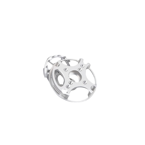
Motor mount frame stiffness is set by the rib layout, not by the plate thickness alone
An aluminum motor mount frame that must hold a 10 kg motor with a 0.05 mm shaft alignment tolerance cannot rely on plate thickness alone for stiffness. A flat 8 mm 6061-T6 plate spanning 200 mm between mounting feet has a first bending natural frequency of roughly 180 Hz—well below the 120 Hz (7200 rpm) excitation frequency of a typical four-pole induction motor. The result is resonant amplification of vibration that transmits noise to the surrounding structure and fatigues the mounting bolts.
The solution is not simply to increase the thickness to 12 mm (which adds cost and weight and only raises the natural frequency to about 270 Hz, still close to the second harmonic at 14400 rpm). Instead, we integrate formed or machined ribs that increase the section modulus in the bending direction without adding proportional mass. A 6 mm plate with two longitudinal ribs 15 mm tall spaced 80 mm apart achieves the same bending stiffness as a 12 mm flat plate with 40 % less material. The ribs are machined using a roughing pass with a large-diameter face mill followed by a finishing pass with a ballnose tool to eliminate stress concentrators at the rib roots—those roots are where fatigue cracks initiate if left sharp.
Bore-to-bore distance tolerance accumulates from the machine’s positioning accuracy, not from the drawing’s nominal
When a motor mount frame has two or more bores that must align with shafts or dowels on both the motor and the base structure, the center-to-center distance between those bores is a critical dimension. The drawing may specify 140 ±0.05 mm, but achieving that consistently requires understanding how the machine’s positioning error contributes.
On a typical VMC with a positional accuracy of ±0.008 mm per axis (bidirectional), the theoretical center-to-center error between two bores machined in the same setup is about ±0.011 mm (root-sum-square of two independent position errors). In practice, thermal drift during the machining cycle (the frame takes 12–15 minutes to complete all operations) can add another 0.01–0.02 mm if the machine warms up between boring the first bore and the last. We control this by allowing a 10-minute warm-up cycle before starting critical dimensions, by machining the most tightly toleranced bores first (while the machine is thermally stable), and by using an in-process probe to verify bore positions before the part leaves the setup. With these measures, we routinely hold ±0.02 mm on center distances over 150 mm spans—half the tolerance band of most drawings, leaving margin for assembly variation.
Flatness of the motor interface face determines whether the motor shaft stays aligned after bolt-up
The face of the mount frame that contacts the motor’s mounting flange (the “motor pad”) must be flat enough that when the four mounting bolts are tightened, the frame does not deflect and pull the motor shaft out of alignment. A flatness error of 0.05 mm over a 120 × 120 mm motor pad, when clamped at its four corners, can induce a shaft angular misalignment of 0.4 mrad (0.023°) at the motor’s flange face—enough to consume 20–30 % of the total coupling misalignment budget before the coupling even enters the calculation.
We machine the motor pad as the last operation before the part leaves the machine, using a fresh insert and a light finishing pass (0.2 mm axial depth of cut) that minimizes cutting forces and thermal distortion. The target flatness is 0.02 mm over the full pad area, verified with a surface plate and dial indicator on every part. For frames larger than 200 mm in any direction where milling flatness alone cannot reliably achieve 0.02 mm, we add a surface grinding operation that brings the flatness to 0.005 mm—the added cost is about 2 minutes per face on a reciprocating grinder and it completely eliminates flatness as a source of alignment error.
Threaded hole position relative to the motor pattern is what prevents cross-threading during field installation
The threaded holes that accept the motor mounting bolts are almost always positioned to match the motor manufacturer’s standard bolt pattern (NEMA, IEC, or custom). If those hole positions are off by 0.2–0.3 mm in any direction—which is within the general positional tolerance of many drawings—the bolts will still go through the clearance holes in the motor flange, but they will enter the threads at an angle. The installer does not notice this because the bolt heads seat against the motor flange and appear tight. What happens is that the first two threads carry all of the load, the bolt is in bending as well as tension, and under vibration the nut works loose or the thread strips.
We hold the true position of motor-mounting threaded holes to 0.1 mm diameter zone at MMC (maximum material condition) relative to the datum reference frame established by the motor pad and the base-mounting holes. This is tighter than most customer drawings specify, but it is necessary for field-reliable installations where the assembler may not use alignment fixtures. We verify true position on the CMM using a best-fit circle through the threaded hole (measured at the pitch diameter, not the major diameter) and report the deviation in both X and Y axes.
Anodize coating on load-critical surfaces must be masked or accounted for in the tolerance stack
Many aluminum motor mounts receive a Type II anodize finish for corrosion protection and appearance. As discussed for other anodized parts in this product family, the coating consumes base metal and builds outward at roughly a 1:1 ratio. On a motor mount, this matters most at the motor pad (where flatness is critical) and at the bore surfaces (where the fit class is critical).
We apply one of three strategies depending on the drawing requirements:
- Mask-and-anodize: Plug the bores and mask the motor pad with silicone before anodizing. These surfaces remain bare aluminum and are treated post-anodize with Alodine (chemical conversion coating) for corrosion protection without dimensional change. Added cost: about 0.08 USD per masked feature.
- Oversize-and-finish: Machine critical features 0.025 mm oversize per side, anodize the entire part, then perform a light re-cut or ream to final size after coating. This removes the anodize layer locally and restores the dimension. Added cost: one additional setup (roughly 3 minutes of machine time).
- Design-for-anodize: Work with the customer to adjust the drawing so that all critical dimensions are specified as “after anodize” with appropriate pre-plate allowances built into the manufacturing notes. This is the lowest-cost option in production but requires drawing revision lead time.
For new programs where the drawing is still flexible, we strongly recommend option 3; for existing drawings with no revision budget, option 1 is usually the most practical.
Vibration damping features reduce transmitted noise by 6–10 dB without adding external isolators
A rigid aluminum motor mount efficiently transmits structural vibration from the motor to the base frame and from there to the surrounding enclosure. For applications where noise is a concern—laboratory equipment, medical devices, office machinery—we can incorporate vibration-damping features directly into the machined frame without requiring separate rubber isolators.
The most effective integrated approach is to machine a pattern of narrow slots (2–3 mm wide, 15–20 mm long) in low-stress areas of the frame web. These slots interrupt the direct transmission path for bending waves, forcing the vibration energy to travel around each slot which introduces impedance mismatches and reflects a portion of the wave back toward the source. A well-designed slot pattern can reduce transmitted vibration amplitude by 30–50 % in the 200–1000 Hz range, which translates to 6–10 dB reduction in measured sound pressure level at a 1-meter microphone position. The slots are added as a single additional profiling operation that takes about 90 seconds of machine time and requires no extra material or assembly steps.
Parts like this one sit under the CNC Machining Parts range, whose overview page gathers the tooling logic, finishing options and tolerance notes shared across the family.
Specifications
| Item | Precision CNC Machined Aluminum Motor Mount Frame |
|---|---|
| Brand | AUNOV |
| Designing | A drawing file or a physical sample starts the review, our engineers reply with a manufacturability assessment and pricing. |
| Tooling | Every die designed and built in our toolroom, held and maintained under your part number. |
| Samples | Samples for approval come with dimensional data and material certification. |
| Materials | Aluminium is the primary stock for this part, alongside carbon steel (SPCC / DC01), 304 / 316 stainless steel, brass and copper, with the final grade confirmed at the drawing review. |
| Surface finish | Plating, e-coat, powder coating, anodising or passivation as the drawing calls out, selected against the drawing requirement. |
| Processing | Staged deep drawing, with in-line annealing where the draw ratio requires, then pierced and machined in house. |
| Equipment | Our press floor runs 5-250 T mechanical and 250-500 T hydraulic presses, CNC cells plus a temperature-controlled CMM room. |
| Tolerance | Tolerances to +/-0.1 mm as drawn, +/-0.03 mm after machining. |
| Delivery terms | FOB is standard; DDP offered for EU and US, T/T or L/C, with D/P for repeat business, call-off schedules supported. |
Related Products


Request a Quote for This Part
Send a drawing or sketch — get material advice, tooling cost and a per-piece price within 24 hours (working days).