
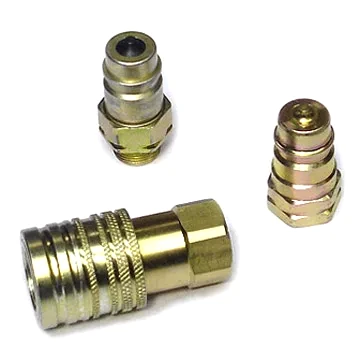
A V-band flange ring is one of the few parts whose clamping force is produced entirely by geometry, and it is one of the few where a single dimension – the included angle of the V – determines whether the joint holds or slips. Everything else about the ring follows from that: the material, the hardness, the surface finish, the number of bolts, the bolt material and the tightening method are all in service of getting two conical faces to sit on each other and stay there.
It is a beautifully simple idea and a surprisingly unforgiving part to make.
The V, and why the angle is the design
A V-band clamp uses the difference between two included angles. The male cone has an angle, the female cone has a very slightly larger angle, and when the band is tightened the cones are pulled together. Because the angles differ, tightening the clamp generates a radial force as well as an axial one, and that radial force is what produces friction over what is a very large contact area.
What follows from the angle difference is the whole behaviour of the joint:
- The clamping force rises steeply with bolt preload. Because the geometry converts axial draw into a large radial compression, a modest bolt torque produces a very large contact pressure at the cones. This is the reason the clamp can hold pressure at all with so few fasteners.
- The contact pressure must not exceed the material’s yield. The V-band’s contact stress is the highest stress in the joint, and it is why the band has a defined material and temper and sometimes a defined hardness, and why the tightening specification is a controlled procedure rather than a “tighten until firm” instruction.
- A larger angle difference gives more clamping force per bolt but a steeper sensitivity to misalignment. There is a practical limit, and going past it means the ring can be cammed or damaged rather than tightened. The angle is therefore a design decision with an optimum, not something to be maximised.
On this part the included angle and its tolerance are the specification. Not the diameter, not the thickness, not the material even. The angle.
Angle tolerance, and the mismatch between the two parts
Two things have to be true for a V-band to clamp properly, and they are not the same thing.
- Each cone has to be at its own correct angle. The male and the female each have a nominal included angle and each has a tolerance band. On a CNC-turned part this is held by the turning operation itself and it is reproducible – this is one of the advantages of a machined ring over a stamped or rolled one.
- The angle difference between the two parts has to be in the usable range. This is the one that is missed. If the difference is too small, the clamp generates very little radial force for a given bolt load and the joint slips. If the difference is too large, the ring is not cammed symmetrically, one side takes all the load, and the joint becomes eccentric – which on a flange means a leak at one side and a stress on the ring at the other.
So the correct engineering statement is not “band angle 60 degrees” but “male angle X, female angle Y, difference Z, with each held to its band, and the difference to be controlled at assembly.” That last clause is where the practical failures live, because the two parts are often made at different times, by different suppliers, or from different lots.
The two ways this gets built, and they are genuinely different products
Two-piece: the male cone is on the flange, the female cone is on the clamp ring
The conventional arrangement. The flange has a male taper machined or forged into it, and a separate ring clamps over it.
- Advantages: the ring is a replaceable wear item, so the expensive part – the flange – is not sacrificed when the ring wears. The joint is inspectable and the ring can be replaced without removing the piping.
- Disadvantages: two manufactured angles have to agree, and the alignment of the two has to be right for the clamping to be even.
One-piece: the V is formed in a ring and both mating faces are straight flanges
A single V-band, sometimes with the sealing faces integral, is used where a quick-release or a lightweight clamp is wanted and where the design can accept the sealing being axial rather than conical.
- Advantages: one angle to control, a lighter assembly, quick to release.
- Disadvantages: less clamping force for the same bolt load, and a sealing surface that has to be flat rather than conical – which means gasket control becomes more important.
Which one is on the drawing is worth stating explicitly, because a machined ring can serve either role and the difference shows up in whether the flange needs a taper.
Sealing, which is the other half of the part
A V-band holds pressure because it compresses something. The seal is usually a gasket – a metal or metal-composite ring, an O-ring, or a wound gasket – and it is the least specified thing on this kind of drawing and it is where the leaks come from.
- The gasket sits in a groove, and the groove’s geometry – its width, its depth, its position relative to the V – is a functional set of dimensions. A groove that is too narrow shears the gasket; one that is too deep allows it to bottom out before the V has clamped.
- Groove position relative to the contact point matters. The gasket must be compressed by the flange faces coming together, which happens before the full V contact is reached on a high-angle design. So the assembly has a defined sequence: gasket contact first, then full V seating, and the clamp’s final torque should be specified with that sequence in mind.
- Surface finish on the flange faces. On a metal gasket seal, the flange face finish is a real requirement and it should be stated with a convention. On an O-ring seal it matters less, but the surface must not have raised burrs that will cut the elastomer.
- Flatness of the flange faces. V-bands are tolerant of some face irregularity because the cone can rock slightly, but gross non-flatness will concentrate the load on the opposite bolt and reduce clamping at the failed side. This is a genuine and frequently overlooked requirement.
Material, and why hardness and temper matter more than usual
Carbon steel, 304 and 316 stainless steel, aluminium and brass are all available, and on a V-band the material decision is about contact stress and about galling at the cone.
- Carbon steel is the traditional material and it is the right one where the joint is large and the service is ordinary. The band is often plated or oiled, and the plating here is again a wear and galling decision rather than a corrosion one.
- Stainless Steel where corrosion is the driver, and specifically where the mating flange is stainless steel – two stainless steel cones rubbing against each other without lubrication will gall, and galling on a cone face is not a cosmetic defect, it is a change of the surface that reduces the clamping and can produce scoring right across the contact band. On stainless steel, specify the surface treatment deliberately.
- Aluminium is occasionally used where weight is critical. It has a much lower yield than steel, so the contact stress limit is reached sooner and the band must be larger or the tightening specification tighter. It also galls readily, and its lower stiffness means it deflects more – on a large band that can mean the cone does not sit evenly.
- Brass and other copper alloys are used in specialised applications, principally where a non-sparking requirement exists. They are soft and they gall; they are not general answers for a V-band.
Two materials notes specific to this application: on a two-piece V-band, the material pairing matters for galling, and dissimilar metals in contact on a cone face will either gall or gall differently depending on which is softer; and where the band is hardened or high-strength, its ductility matters because a V-band that is too hard will crack at the bolt lugs rather than spread evenly, and the lugs are the highest-stress region on the part.
Machining it
Turning, milling and drilling sequenced to minimise handling and re-chucking is the right route, and on this part the sequencing has a specific reason: the angle is produced by the turning operation and the angle is the specification. So the cone should be cut in one setup, and ideally the clamping for the rest of the part should not disturb the cone afterwards.
Three practical points on the machining:
- The bolt lugs and the cone are in tension together. The bolts pull the lugs and the lugs pull the cone into contact. If the lugs are machined after the cone and the chucking or the fixture holds on the cone, the angle can be disturbed. Machining the lugs first and the cone last, from a datum that references the body rather than the cone, is the safer sequence.
- The cone’s surface finish affects clamping. A cone turned to a moderately fine finish grips better than a polished one, because the friction is higher. This is a genuine trade: a polished cone looks better and clamps worse. On a V-band the finish is functional and should be specified as such, with an allowance for the plating or coating that will follow.
- The angle’s tolerance is best held by the machine’s own geometric control. On a CNC lathe the included angle over the cone’s length is a function of the tool path and it is repeatable. This is one of the cases where machining is genuinely better than the alternatives, because a rolled or formed band cannot hold an angle to a band across its length.
Tolerance, allocated to the clamping
+/-0.01 mm on critical bores is achievable and is confirmed at the DFM stage, with critical dimensions carrying CMM data with the shipment. On this part the allocation is unusual: the tightest dimensions are angles and flatnesses rather than sizes.
- Included angle of the male cone, held to a stated band, measured over the full length of the cone rather than at one point – a cone that is right at the small end and wrong at the large end will not clamp evenly.
- Included angle of the female cone, same requirement.
- Groove dimensions – width, depth, and position – held to their own bands, because they set the gasket’s compression.
- Flatness of the flange faces and their perpendicularity to the part’s axis.
- Concentricity of the bolt pattern to the part’s axis, so that the clamping load is symmetric.
- Overall dimensions and the bore at a general band. The bore’s function here is to locate the ring on the flange, so its fit matters, but its absolute size usually does not.
Included angle of both cones is the check not in the standard set
- Included angle of both cones, measured at multiple positions along the cone – this is the inspection that matters on this part, and it is not in the standard inspection set.
- Effective angle difference, ideally verified against the mating part on a sample basis, because two parts that each meet their own tolerance can still be outside the usable difference.
- Groove dimensions on every part, and a visual check that the groove is free of burrs and sharp edges that would damage a gasket.
- Flange face flatness and finish.
- CMM data on the critical bores and the pattern with the shipment.
- Surface treatment thickness and adhesion on the first article, with the cone’s coating condition stated – and a note that a coating on the cone changes the effective angle slightly and the friction behaviour a great deal.
- On the assembled joint, where a first article is available: tighten to the specified torque, measure the gap between the flange faces at several points around the circumference, and confirm it closes evenly. This is the functional acceptance test, and on a part whose whole purpose is to clamp evenly it is the most informative check available.
Expected bolt preload, and whether the method is controlled
What bolt preload is this clamp expected to produce, and is the tightening method controlled – a torque wrench with a stated value, a hydraulic tensioner, or eyeballs and a rule of thumb? The clamp’s entire function is a controlled radial force, and a V-band tightened to the correct torque and a V-band tightened until it feels right will differ by a large factor in clamping force, with the band at risk in the second case and the joint at risk in both if the load is too low. This one question determines whether the band’s material and thickness are adequate, whether the specified torque is achievable with the bolts proposed, and whether the installation instructions need to be treated as part of the product. It is a question about the assembly rather than about the ring, and on this part it turns out to be the more important one.
Parts like this one sit under the CNC Machining Parts range, whose overview page gathers the tooling logic, finishing options and tolerance notes shared across the family.
Specifications
| Item | CNC Machined V-Band Flange Ring |
|---|---|
| Brand | AUNOV |
| Designing | Quotation reflects the real drawing: tolerances, finish and features are priced as specified. |
| Tooling | Die design and toolmaking stay in house, so die cost stays transparent, and first-article timing is measured from the tooling start date. |
| Samples | Any sample deviation is corrected before the first production batch is released. |
| Materials | Stock covers carbon steel (SPCC / DC01), 304 / 316 stainless steel, aluminium and brass; mill certificates and heat numbers accompany the first article. |
| Surface finish | Surface treatment matched to the duty: plating, coating or polishing; the agreed finish travels with the part number. |
| Processing | Turning, milling and drilling sequenced to minimise handling and re-chucking; in-process checks sit between stages, not only at the end. |
| Equipment | CNC turning centres with bar feeders and 3-/4-axis machining centres, with in-house toolmaking to keep dies and fixtures maintained. |
| Tolerance | +/-0.01 mm on critical bores, confirms at DFM stage; critical dimensions carry CMM data with the shipment. |
| Delivery terms | Standard terms FOB; DDP available for EU and US, with T/T and L/C accepted. |
Related Products


Request a Quote for This Part
Send a drawing or sketch — get material advice, tooling cost and a per-piece price within 24 hours (working days).