
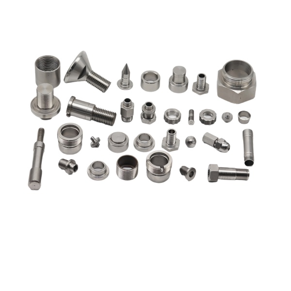
The Assorted Stainless Steel CNC Turned Fittings and Cones family is dominated by one geometry: the sealing cone, the machined taper that carries the joint’s entire sealing duty on a narrow band of contact. Everything else on the fitting – the collar, the flats, the thread – exists to clamp that cone into its mate. This page covers why a cone’s angle error converts directly into contact stress and leak behaviour, how a true taper is actually turned, what the tool nose radius does to the sealing surface, how the wrench features are produced without wrecking the cone, and the verification that ships with each batch.
A sealing cone carries load on a narrow band, so angle error becomes stress
When a cone with an included angle in the standard range seats into its mating cone, the contact is intended to be a continuous band around the circumference. The geometry is unforgiving: if the two angles differ by even a fraction of a degree, contact collapses to the edge of the band – at the large end or the small end depending on the error’s sign – and the full clamping force lands on a line instead of an area. Line contact means local stress far above what either surface was designed for, which work-hardens, gouges or cracks the seat on stainless steel, and after one assembly the fitting may never seal cleanly again. This is why cone angle is not a cosmetic dimension: it is the joint.
- We hold cone angles by machine geometry and verified setup rather than by hope – the taper is turned with the compound or the machine’s taper interpolation proving the angle to a sine-bar or CMM check on the first article, because a half-degree error looks fine and leaks.
- The mating half’s angle is the other half of the problem: where the customer controls the seat, we state our angle tolerance at quotation so both sides can be designed to close the stack rather than each assume the other.
- Axial position of the cone matters as much as angle – a cone that is dimensionally perfect but sits 0.2 mm short of its designed engagement bottoms the thread before the cone contacts, and the joint “tightens” with nothing sealed.
- Surface damage on the band is treated as a reject rather than a rework wherever the duty is pressure, because a polished-over gouge in a work-hardened stainless steel seat is a leak with a delay timer.
Turning a true taper: generated angle versus interpolated angle
There are two ways a lathe produces a taper, and they fail differently. Swivelling the compound or using the machine’s built-in taper generation cuts a true cone from machine geometry – the angle is whatever the setup proves it to be, and it is consistent for the full length. Interpolating the taper on a driven tool or a milling path approximates the cone from the machine’s linear axes, and the approximation shows as faceting or dwell marks at the path transitions unless the interpolation step is fine enough. On a sealing cone, either method is acceptable; what is not acceptable is an unverified one.
- First article gets the cone angle measured on the CMM or checked against a certified setting master, and the measurement – in degrees or taper-per-length, matched to the print’s convention – is the number the batch is accepted against.
- The finishing pass runs the full cone length without interruption, because a pass that stops and restarts mid-taper leaves a step at the restart, and a step inside a sealing band is a permanent leak path.
- The cone is finished before the features that clamp it, so nothing downstream bends, dings or re-clamps the finished surface.
- Where a fitting carries two coaxial cones, both are cut in one setup and their mutual relationship is reported, since a joint can only seal on the cone the geometry actually aligns.
Tool nose radius leaves the finish, and the finish carries the seal
The surface finish on a sealing cone is generated almost entirely by the tool nose radius and the feed per revolution: the theoretical Ra of a turned surface is a direct function of those two, and on a sealing band the target is typically Ra 0.4 or better. The trap is that a feed chosen for cycle time on a bar-facing operation leaves a finish that is visually acceptable and functionally marginal – the scallops between passes become the leak paths under low pressure, and polishing afterward to chase the finish destroys the diameter control that the cone angle depends on.
- We select nose radius and feed as a pair to hit the specified finish by geometry, and we verify the finish on the first article by profilometry on the sealing band, with the reported value, not a visual grade, closing the loop.
- The last pass on the cone uses a fresh edge – nose wear widens the effective radius, which improves finish while quietly growing the diameter at the small end, so tool-life counts protect the geometry as much as the surface.
- Vibration control matters on slender fittings: even fine chatter that depth gauges cannot find shows instantly in a profilometer trace as periodic peaks, and a chatter-marked cone cannot be re-cut without disturbing the angle.
- Where the print asks for a burnished or lapped seat beyond turned capability, we quote it as a separate operation rather than pretending a finishing pass is a lap.
Collars, flats and hex features must not drag the cone with them
A cone fitting usually carries wrenching features – hex sections, spanner flats or a collar – and turning the flats or milling the hex after the cone introduces a sequence risk. Cutting flats removes material asymmetrically, and on a thin-walled stainless steel fitting the relieved side relaxes differently from the uncut side: the part bows a few hundredths, and the cone that was concentric before milling is now eccentric to the thread. The error is small, but the sealing band’s tolerance is smaller.
- We cut wrench features before the cone’s finishing pass wherever the sequence allows, so the last operation on the sealing surface is the one that establishes it.
- Where the geometry forces flats after the cone, the flat depth is kept balanced across the feature and the cone’s concentricity is re-verified afterward instead of inherited from the earlier setup.
- Collars are turned in the same setup as the cone, and the collar’s face squareness is reported because the collar transmits the clamp load that seats the cone – a tilted collar seats the cone unevenly around the circumference.
- Knurled or serrated collars follow the same forming rules as any knurl: pitch-matched feed on the first article, and the diameter measured over the formed ridges.
How we verify cone angle and sealing condition on turned fittings
Verification for this family centres on the two numbers that decide whether the joint seals: the cone’s angle and its surface condition. Each release ships with:
- Cone angle measurement on the first article by CMM, reported in the print’s convention, with production batches verified against the same setup master on the sampling plan.
- Surface finish on the sealing band by profilometry on the first article and sampled in production, reported as Ra values against the print.
- Concentricity of cone to thread and collar checked by rotation under an indicator or on the CMM, because an eccentric cone seals on one side only.
- Thread gauging with go/no-go per the plan, pitch diameter measured on the first article, and thread engagement-to-seat relationship verified where the print defines it.
- Wrench feature integrity – flat depth, hex size and collar squareness – on the sampling plan, with damage from handling treated as reject on a pressure-duty fitting.
- Passivation record per ASTM A967 with the free-iron test result, plus material certificates per heat, archived with the first-article report under the part number.
Repeat orders restart from the archived programs, tool-life limits and setup masters, so a cone turned a year later seats against the same geometry and finish that won the first article’s approval.
CNC Machining Parts is the parent range for parts like this one; the overview page gathers the tooling logic, finishing options and tolerance notes that apply across the family.
Specifications
| Item | Assorted Stainless Steel CNC Turned Fittings and Cones |
|---|---|
| Brand | AUNOV |
| Designing | Send us your 2D drawing, or mail a sample for measurement, the quotation comes back with a manufacturability review attached. |
| Tooling | Every die designed and built in our toolroom, with your part number on the tool record. |
| Samples | Sample parts arrive with dimensional data and material certs. |
| Materials | 304 / 316 stainless steel is the primary stock for this part, alongside carbon steel (SPCC / DC01), aluminium, brass and copper, and the grade is fixed at the drawing review. |
| Surface finish | Plating, e-coat, powder coating, anodising or passivation, as called out on your print. |
| Processing | Deep drawing in stages, in-line annealing where needed, pierced and machined on the same floor. |
| Equipment | Mechanical presses 5-250 T, hydraulic presses 250-500 T, CNC cells plus a temperature-controlled CMM room. |
| Tolerance | Tolerances to +/-0.1 mm as drawn, +/-0.03 mm on machined features. |
| Delivery terms | FOB standard, DDP offered for EU and US, T/T and L/C; D/P on repeat accounts, blanket orders and call-offs supported. |
Related Products


Request a Quote for This Part
Send a drawing or sketch — get material advice, tooling cost and a per-piece price within 24 hours (working days).