
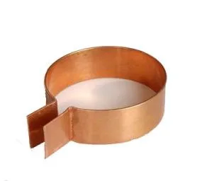
A plate or a bracket milled from aluminium looks like the simplest thing in this catalogue, and that is exactly why it is worth writing about properly. When a part is milled from solid bar or plate, you are not shaping a material – you are deciding how much material to remove, and every decision about how much to remove is a decision about what the finished part will do.
The four questions that decide a milled plate or bracket are the ones that decide any machined part: how much of the stock is going to become chips, how many times does the part have to be set up, which direction does the load go, and what is the part’s tolerance actually for. Getting these four right is the difference between a bracket that costs a few cents and a bracket that costs a few dollars and fails at the third customer.
Bar, plate, or a part that is closer to finished
The stock choice on a milled bracket decides more than the price. It decides the fibre direction, the machine time, and the achievable tolerance in a way that is not obvious from the outside.
- Plate is rolled or cast flat. Its properties are close to isotropic in the plane and different through the thickness, and it is the right choice for a part whose geometry is genuinely a flat shape. It is also the only option when the part has to be a plate – a mounting plate, a shim stack component, a cover – because you cannot make a plate from bar economically.
- Bar or billet is drawn or forged round or square. Drawn bar has a clear directionality from the drawing process; forged billet has finer, more uniform grain and better fatigue properties. On a bracket whose load path runs along the length, forged or heavily drawn stock in the right orientation will outlast the same part cut from a plate rolled the other way.
- Extrusion is a legitimate and often overlooked option for a bracket. An extruded profile with the correct cross-section removes the question of how to machine the outline at all, at the cost of a tooling charge and a minimum order. For a simple L or channel section at volume, it is usually the cheapest route by a wide margin. It is worth asking whether the bracket’s cross-section could be extruded, because on many brackets it can.
And the fourth option, which is sometimes the right answer for a plate part: a stamped or deep-drawn bracket, then machined. If the outline, the holes, and the bends can all be made in a die, and only a small number of features need machining afterwards, the combination is usually cheaper than either pure approach. It also changes the tolerance picture entirely, because a stamped outline has a tolerance that does not tighten for free.
Cost is decided by setups and by what the tool is cutting
Machining time on this part is not proportional to the number of features. It is proportional to setups multiplied by the time in each. Two setups of four minutes each costs eight minutes plus two loadings; one setup of ten minutes costs ten. This is why the drawing’s feature grouping matters, and it is why “as few setups as the geometry allows” is the correct processing instruction rather than a slogan.
On a milled bracket, three things drive the time:
- How many directions the tool has to approach from. A bracket with all its features on one face and one side is a three-axis job. The same bracket with a hole in a bottom face and a boss on the far side is a four-axis job at best, and if the far-side features have to be reached from an awkward direction it is a five-axis job. This is where the cost cliff is, and it is visible in the geometry long before it is visible in the quote.
- How much material has to come off to reach the finished size. A bracket milled from 25 mm stock down to 4 mm sections spends most of its cycle removing air. Roughing a large cavity is fast; finishing the walls and the bores is what takes the time. Thinner starting stock is usually a cheaper part, not a more expensive one, even when the stock price per kilogram is higher.
- How far the tool has to reach, and how long the cutter sticks out. A slender cutter reaching into a deep pocket deflects, and the deflection becomes error. The same feature can be made as a through-hole from the other side, or as a shallow feature with a step, and the choice changes both the cost and the accuracy.
Bar-fed turning centres plus three- and four-axis machining centres cover this work well, and in-process inspection between stages rather than only at the end is what catches a tool that has started to wear before it has produced a batch of undersized parts.
The load path, which is what the bracket is actually for
A milled bracket in aluminium is a stiffness question far more often than it is a strength question. Aluminium’s yield strength is fine; what limits a thin aluminium bracket is usually deflection, and deflection is a section property problem rather than a material property problem.
Three things follow from that, and each of them is a drawing decision:
- Put material where the bending moment is. A bracket fails by bending first at the section furthest from the load, and the further that section is from the neutral axis, the more useful every gram is. Deepening a flange at the base of a bracket is worth far more than adding material around the bolt hole. This is the single most common improvement available to a thin aluminium bracket.
- Widen the section in the direction of the load, not across it. A section’s stiffness scales with the square of its depth and only linearly with its width. Doubling a width gives about twice the stiffness; doubling a depth gives about four times. If a bracket is being made too weak, this is the first thing to check.
- Keep the grain direction aligned with the load where the stock allows it. Aluminium extruded or drawn in one direction is meaningfully stronger and stiffer in that direction. On a bracket loaded in bending, the fibre direction should be along the load.
The failure mode to watch on a milled aluminium bracket is not tensile failure. It is a bolt hole elongating, a fillet radius cracking at the corner of a pocket, or the part flexing enough to let a fastener loosen. All three are stiffness and stress-concentration problems, and all three are fixed in the geometry rather than in the alloy.
Fillet radii and the difference between a drawing value and a machined value
Machined fillets are not decorative. They are the difference between a bracket that survives a million cycles and one that crack at a corner in a few thousand.
Three things about them are worth stating properly:
- The minimum internal radius must be larger than the tool radius that produced it. A 2 mm corner cannot be milled with a 3 mm cutter, so it becomes a stepped corner with the cutter’s own relief marks, and that is where the crack starts. Drawing 2 mm corners on a part machined with 6 mm tooling produces exactly that geometry.
- Where a radius meets a flat, say so, because the intersection of a milled radius with a face is a geometric discontinuity that a stress model will find and a hand calculation will miss.
- Distinguish a machined radius from a formed one. On a part with any cast, forged, or as-extruded feature, the radii there are inherited from that process and are not under the machining drawing’s control. A bracket with a cast root and a milled flange has two different fillet qualities and two different fatigue lives, and the drawing should say which is which.
Tolerance, decided by function rather than by habit
+/-0.005 mm is achievable on ground faces where the print demands it, and it is worth spending only where the function needs it. A sensible allocation on a milled bracket looks like this.
- Bolt and pin holes: size, position and, where a fastener sets the location, position relative to the mating face rather than to the machine origin. A hole that is in tolerance but not in the right place relative to the face it clamps against is a hole that will not fit.
- The mounting face, in flatness and in a small amount of parallelism or perpendicularity to the hole pattern. On a bracket, the mounting face flatness often matters more than any dimension on it, because it is what the whole part registers on.
- Critical sections: thickness or section depth, where stiffness depends on it. This is a dimension that is easy to omit and expensive to get wrong, because a thin section on a strong machine is often under the tool’s ability to hold, and the variation shows up as a variation in stiffness rather than as a reject.
- Positions between features that must stay related, held as position tolerances rather than as coordinate dimensions. This is more honest and it is easier to inspect.
- General lengths and widths at a general tolerance. This is where the tolerance budget is recovered.
Materials, and the substitution question
Carbon steel, 304 and 316 stainless steel, aluminium and brass are all available on this route, and substitutions are proposed only in writing, which is the correct way to handle it. The substantive point is that a bracket designed in aluminium and then re-specified in stainless steel is not a like-for-like substitution: it will be three times as heavy, it will be stiffer in absolute terms and no stiffer in relative terms, it will fatigue differently, and it will need a different corrosion strategy. Sometimes stainless steel is right – a marine bracket, a food-adjacent bracket, a bracket that must not galvanically couple to something else. But it should be a decision rather than a default.
For aluminium specifically, the temper matters more than most buyers expect. A 6061-T6 part and a 6061-T4 part are the same alloy at different strength levels, and for a milled bracket where the material is being cut heavily, the free machinability of the T6 condition is worth real cycle time. Where the bracket then receives a heat treatment or a coating that changes the temper, that needs to be in the routing.
Surface finish and adhesion
Plating, coating, anodising or passivation, with thickness and adhesion checked on the first article. On a milled bracket, anodising deserves a specific caution: an anodised surface is thicker than the substrate it sits on, so any hole that has to accept a fastener and any face that has to register against something needs to be either masked or dimensioned post-anodise. Powder coating similarly adds a meaningful film thickness, and on a hole that has to take a bolt, the coating fills the hole before the bolt does.
On a milled bracket, the items that must be masked are the datum faces, any thread, any sealing face, and any hole whose size matters. Naming them on the drawing is the difference between a bracket that fits after finishing and one that does not.
The two numbers worth reporting on a milled bracket are flatness and hole position
First articles and batch samples on the CMM, with the critical dimensions carrying data. For a milled bracket the honest reporting includes the flatness of the mounting face and the position of the hole pattern relative to it, because those two are the functional ones and they are the two most likely to be substituted for a general tolerance in a hurried release.
In-process checks between stages matter more here than on a simpler part, because the tool-wear mode on aluminium is gradual and a batch can be entirely within size while every part in it is at the wrong end of the wear band. Catching that at the third part is much cheaper than catching it at the three-hundredth.
Extruded, or stamped with a small machined operation
Could this bracket be extruded, or stamped with a small machined operation afterwards, instead of milled from solid? On a bracket with a constant cross-section, an extrusion is usually cheaper at volume than milling, and a stamped-and-machined part is usually cheaper at almost any volume. Neither option wins on tolerance – a milled bracket will hold tighter than either – so the real question is whether the tolerance you are holding is the one the joint needs. On a lot of brackets it is not. A stamped bracket at +/-0.15 mm on its outline with a machined pad at the bolt holes will usually outperform a fully milled bracket at a lower cost, and the fully milled option is only justified when something about the part genuinely needs it.
This part belongs to our CNC Machining Parts range. The cnc machining parts pages collect the process notes, common materials and inspection points behind every product in the family.
Specifications
| Item | Custom Aluminum CNC Milled Plates and Brackets |
|---|---|
| Brand | AUNOV |
| Designing | Made to your 2D/3D drawings (PDF, DWG, STEP, IGS) – unusual walls, threads or tolerances are feasibility-checked first; changes are priced before they are made. |
| Tooling | Dies are made and maintained in house, which keeps tooling lead time and cost under control. |
| Samples | Production does not start until the sample report has been signed off. |
| Materials | Stock runs to carbon steel, 304 / 316 stainless steel, aluminium and brass; material substitutes are proposed only with your written approval. |
| Surface finish | Surface treatment matched to the duty: plating, coating or polishing; finish thickness and adhesion checked on the first article. |
| Processing | CNC turning with milling and drilling in as few setups as the geometry allows; in-process checks sit between stages, not only at the end. |
| Equipment | Bar-fed CNC turning centres plus 3- and 4-axis machining centres, backed by CNC turning centres and a climate-controlled inspection room. |
| Tolerance | +/-0.005 mm achievable on ground faces where the print demands it; capability is checked on the first article before the run continues. |
| Delivery terms | CIF or DDP, with FOB available, payment by T/T or L/C, quoted in USD or EUR; repeat orders reuse the approved first article. |
Related Products


Request a Quote for This Part
Send a drawing or sketch — get material advice, tooling cost and a per-piece price within 24 hours (working days).