
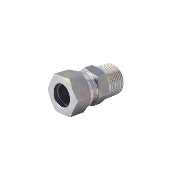
A hex nipple’s two threads are cut in one setup, and that’s why they stay concentric
A hex nipple fitting—two male threads joined by a hex body—must have both thread axes collinear, or the piping on either side will be stressed into misalignment as the nipple pulls the two runs together. A run-out of 0.2 mm between the two thread axes on a 200 mm pipe span imposes a bending load on every joint downstream.
We cut both threads in one lathe setup (part held in a hex collet, first thread cut, stock repositioned by tailstock support if the length requires, second thread cut without unclamping). Thread-to-thread concentricity is held at 0.02 mm TIR, verified on a threaded arbor with an indicator on each thread’s pitch diameter. Nipples machined in two setups (a corner-cut some shops take for long parts) typically show 0.1–0.3 mm run-out—fine for low-pressure plumbing, unacceptable for instrument lines.
Thread engagement on both ends consumes the pipe’s alignment budget twice
A nipple threads into two female components, and each thread connection has its own fit clearance and tightening-induced alignment error. The nipple’s hex length gives the installer wrench access but also fixes how much angular position each end can take: as one end is tightened, the nipple rotates, and the second end’s starting angle is whatever the first end leaves it.
For alignment-critical runs, we machine nipples with a shoulder on one end: the shoulder seats against one component’s face (fixing that end’s angular and axial position), and only the second end’s thread is tightened to pull-up. This converts the alignment error from “sum of two random threads” to “one thread plus one flat shoulder”—typically halving total misalignment. The shoulder’s face is machined perpendicular to the thread axis within 0.03 mm per 10 mm of face diameter in the same setup as the threads.
The wrench flats must carry the make-up torque of both ends
On a nipple, the hex does more work than on a single-ended fitting: the installer holds the hex to make up the first end, then uses it again to make up the second end into the first assembly. The hex sees the full torque of the second connection reacted through the first—which means the hex’s corner strength matters twice over.
We size hexes to standard across-flats dimensions for the thread size (per ASME B18.2.2 or ISO 4032 equivalents), which for stainless steel nipples gives a torque margin of roughly 2× the standard make-up torque. On designs with a reduced hex (for tight-clearance installations), we note the make-up torque limit on the installation sheet and recommend the second end be made up by holding the adjacent pipe run’s fittings, not by loading the undersized hex beyond its limit.
Flow-through bore: chamfering both ends without losing wall strength
The nipple’s bore is a flow path, and its ends are where the fluid transitions from the mating component into the nipple. Sharp bore edges at the thread ends generate turbulence and, in tubing systems carrying particulate, erode at the edge.
We chamfer both bore ends (0.5 × 45° typical) in the same setup as the threads. The chamfer must not eat into the thread’s minor diameter: on a thin-wall nipple (bore diameter approaching the thread minor diameter), the chamfer is reduced to 0.3 mm or replaced by a radius, and the wall between bore and thread minor is verified on the first article by section—one measurement per design—since no external gauge can see it.
How we verify hex nipple fittings before shipping
- Threads both ends: Go/no-go ring gauges per class on 100 % of parts; pitch diameter measured with thread micrometers on every 25th part.
- Concentricity: On a threaded arbor, indicator at each end’s thread pitch diameter and at the hex: 0.02 mm TIR acceptance.
- Hex: Go/no-go across flats; width across corners sampled to confirm corner integrity.
- Bore: Plug gauge for size; visual on both chamfers (no burrs protruding into the flow path).
- Shoulder face (if designed): Flatness ≤ 0.02 mm; perpendicularity to thread axis ≤ 0.03 mm per 10 mm diameter.
- Pressure test (sample): One nipple per batch made up between two master fittings at standard torque, pressurized 1.5× rated, 10 minutes. Disassembly torque recorded as reference data for the customer’s maintenance documentation.
This part belongs to our CNC Machining Parts range. The cnc machining parts pages collect the process notes, common materials and inspection points behind every product in the family.
Hex geometry: flat versus corner strength
A hex nipple is tightened on its flats, but it fails at its corners if the corner radius is too small or the flat width is too tight for the wrench. We set the flats to the standard wrench size and then choose the corner radius for strength under make-up torque, because a sharp-cornered hex cracks before a rounded one does. The hex is cut in the same setup as the threads so the two stay concentric, which is why a nipple spun onto a gauge seats square instead of cocking. We check the flat width and the across-corners together rather than trusting one.
Passivation and what it does not do
Passivating a stainless steel nipple cleans the surface and restores corrosion resistance after machining, but it does not add a coating and it does not hide a bad finish. We passivate every stainless steel fitting as standard and we are clear that it is a surface treatment, not a protective layer, so the buyer does not expect it to survive abrasive service. Where the environment is harsh we specify a different grade or a real coating upstream, because passivation is the floor, not the shield.
Specifications
| Item | Stainless Steel CNC Machined Hex Nipple Fitting |
|---|---|
| Brand | AUNOV |
| Designing | Send drawings, or send a fitting sample to be measured, DFM feedback is returned with the quote. |
| Tooling | Dies engineered and produced in our own toolroom, held and maintained under your part number. |
| Samples | First-off samples of the fitting are sent with dimensional data and material certs. |
| Materials | Stock for this part leads with 304 / 316 stainless steel, alongside carbon steel (SPCC / DC01), aluminium, brass and copper, per the drawing. |
| Surface finish | Surface treatment per the drawing: plating, e-coat, powder coating, anodising, passivation, as called out on your print. |
| Processing | Deep drawing in stages, in-line annealing where needed, then pierced and CNC-machined in house. |
| Equipment | Press capacity from 5 to 500 T across mechanical and hydraulic lines, CNC turning centres, climate-controlled CMM room. |
| Tolerance | As-drawn tolerance +/-0.1 mm, +/-0.03 mm after machining. |
| Delivery terms | FOB as standard, DDP available for EU and US destinations, T/T and L/C; D/P on repeat accounts, call-off schedules and blanket orders supported. |
Related Products



Request a Quote for This Part
Send a drawing or sketch — get material advice, tooling cost and a per-piece price within 24 hours (working days).